


TABLE OF FIGURES
Figure 1: Condense Drain.........................................................3
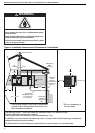
Figure 2: Installation Clearances and Clearances to
Combustibles.............................................................4
Figure 3: Suspension Methods .................................................9
Figure 4: Flue and Roof Detail ................................................ 10
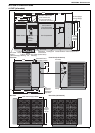
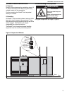
Figure 5: Control Section & Upper Panel ................................ 11
Figure 6: Alternate .................................................................. 11
Figure 7: Vertical and Horizontal Flue Termination -
Type B
22
Appliance...................................................12
Figure 8: Vertical and Horizontal Flue Termination -
Type C
12
C
32
& C
62
Appliances..................................12
Figure 9: DualAir
®
Units Installed in Isolated
Equipment Rooms...................................................13
Figure 10: Ducting................................................................... 14
Figure 11: Gas Connection with Stainless Steel
Flex Connector.......................................................15
Figure 12: Automatic Burner Control Box Sequence...............22
Figure 13: Modureg Gas Valve................................................22
Figure 14: Heater Operating Sequence ..................................25
Figure 15: Fan/Limit Thermostat .............................................25
Figure 16: Belt Tension ...........................................................27
Figure 17: Standard Regulator Removal.................................35
Figure 18: Cooling Coil Safety Devices...................................40
Figure 19: Combination Fan/Limit Thermostat........................43