


SECTION 8: UNITARY LINEAR & U-TUBE HEATER INSTALLATION
17
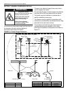
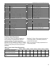
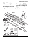
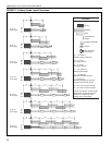
8.4 Unitary U-tube Heater Layouts
CTHN-Series heaters (except CTHN-40) are
approved for optional u-tube configurations.
The u-tube may be installed in either a standard
horizontal position, 45° position or in an opposite 45°
position as shown on Page 5, Figure 5 through
Figure 7. When using a u-tube configuration, the
following additional rules must be adhered to:
• A minimum of 10' (3 m) on CTHN-60/80, a
minimum of 15' (4.5 m) on CTHN-100/125, and a
minimum of 20' (6 m) on CTHN-150/175/200 is
required between the burner and the u-tube.
• For turbulator installation, See Page 21, Step 8.8.
• The burner must never be operated
in a tilted position.
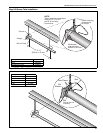
The heater must be properly supported at all
locations. See Page 10, Figure 12.
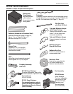
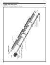
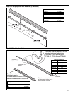
FIGURE 16: U-tube Assembly Overview
U-tube
18" (457 mm)
Center to Center
U-clips
Reflector
End Caps
12
12
1
2
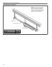
U-tube, Full 45°
12
Burner
Reflector
Turbulator
(With Select
Models)
Tube Clamp
Package
Burner
Tube
Tube
U-tube
Support Bracket
Reflector
Support
Couplings
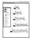
U-tube, Standard
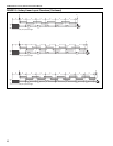
U-tube, Opposite 45°
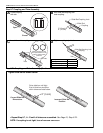
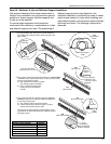
Nut
Lock Washer
Lock Washer
Nut
U-bolt
Tight U-bolt
4" (10 cm) u-bolt,
secured to burner tube
with 1/4" (6 mm)
lockwashers and
1/4-20 hex nuts.
Loose U-bolt
4" (10 cm) u-bolt,
secured to bracket with
1/4" (6 mm) lockwashers
and 1/4-20 hex nuts on
top and bottom to
allow for tube expansion
and contraction.