


SECTION 3: CRITICAL CONSIDERATIONS
3
SECTION 3: CRITICAL CONSIDERATIONS
3.1 Basic Information
CTCU heaters have automatic ignition burners for
ON/OFF operation only.
3.2 Location and Suspension
All models:
• Must be installed indoors.
• Must be installed in a level position with horizon-
tal or vertical discharge.
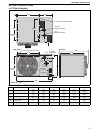
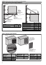
• May be mounted on a shelf of non-combustible
material. (See Page 5, Section 4 and Page 7,
Figure 2 for support points.)
• May be suspended from above (See Page 7, Fig-
ure 2) or from wall brackets of sufficient strength
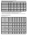
to support the heater as listed in the Dimension
Data Table on Page 5, Section 4.1. Drop rods
must be a minimum of 10 mm diameter mild
steel. Four suspension points (M10 nuts) are
located on top and back side of the heater.
• Must be installed in a manner which allows
access to all serviceable components.
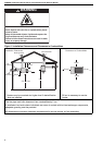
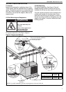
3.3 Minimum Required Installation Clearances
Clearances around the heater and flue must be as
indicated on Page 4, Figure 1; Page 9, Figure 5
through Page 10, Figure 7 to ensure access for
servicing, and correct operation.
3.4 Clearances to Combustibles
Clearances must be as indicated on Page 4, Figure
1. If clearances to combustibles are not indicated,
then installation clearances apply.
3.5 Ventilation
It is important to ensure that there is adequate air
circulation around the heater to supply air for
combustion, ventilation and distribution in
accordance with local and national codes.
3.6 Gas Supply
It is important that the gas supply pipe is sized
correctly to provide the inlet pressure as stated on
the heater data plate. The gas supply pipe and
electrical connections must not support any of the
heater's weight.
3.7 Electrical Supply
A permanent 230 V 50 Hz 1 Ø electrical supply is
required at the main electrical terminals. The heater
also requires suitable energy controls in accordance
with Section 9.
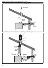
3.8 Flue
Choose heater siting to allow for the proper location
of the flue. Each heater must be fitted with an
individual and correctly sized sealed flue system
(See Page 9, Section 6).
No other appliance may be connected to the flue.
For room sealed installation, the air intake must be
the same size sealed system and the flue/air intake
must terminate at an approved concentric wall or
roof terminal.