


SECTION 10: COMMISSIONING
17
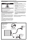
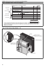
10.2.2 Commissioning the Gas Valve (All Gases)
10.2.2.1 Check Burner Gas Pressure
1. Loosen the screw cover of the outlet (burner)
pressure test point and connect a manometer.
2. With the burner firing, measure the pressure on
the manometer. To adjust the burner pressure,
remove the regulator cover from the valve and
turn the regulator adjustment screw to set the
required burner pressure as stated in the Tech-
nical Data Tables for the correct gas and model
on Page 6, Section 4.3.
NOTE: If the correct burner pressure cannot be
reached, then check the inlet pressure to the valve,
with the burner firing. See Technical Data Tables on
Page 6, Section 4.3 for inlet pressure requirement.
Do not continue to adjust the regulator if the
pressure is not changing.
If the inlet pressure is too low to allow correct burner
pressure setting, then the gas inlet pressure must be
corrected before completing the commission.
Check Gas Rate
1. After burner pressure adjustment, allow the
heater to operate for at least 15 minutes and
then re-check settings.
2. Remove the manometer and refit all covers to
the valve and tighten the screw of the outlet
pressure tap.
3. Check gas flow rate at gas meter.
10.2.3 Combustion Testing
The only adjustment to alter combustion
performance is burner pressure. Combustion quality
must be tested to prove correct heater operation.
Incorrect results will indicate faults with the
installation or appliance.
Combustion testing must be carried out with all
covers in place. The flue gas is sampled in the flue,
within 1 meter of the heater. The values of CO
2
should be between 5.7% to 8.0% for natural gas and
6.8% to 9.2% for LPG dependant upon model.
The CO will be up to 80 ppm (0.008%) dry, air free
dependant upon model. Temperature rise of the flue
gases above ambient should be approximately
130° C to 160° C. Seal test hole in flue after testing.
10.2.4 Pressure Switch
The pressure switch is factory pre-set for each
model and is not adjustable.
10.2.5 Turning Off the Heater
Set the external controls to the "OFF" position and
the main burner will stop.
The fan will run until it is stopped automatically by
the fan thermostat.
Do not use Electrical Isolator for control of
heater. Electrical Isolator will switch off the fan.
Heat exchanger could be damaged. Warranty will
not cover damage to the heat exchanger if
operated improperly.
10.2.6 External Controls
External Controls may include time switch, room
thermostat and frost thermostat. Operate each
control to ensure that they function correctly. Set the
time switch (if fitted) and room thermostat to the
users’ requirements.
10.3 Complete the Commissioning
Ensure that all covers are fitted correctly and all test
points are properly sealed.
10.3.1 Instruction to the User
Explain the controls of the heater to the user
including how to turn it on and off, using the controls
fitted on site.
Give this manual to the user.
Ensure that the user is shown and understands the
importance of maintaining clearances to
combustibles and the user instructions on Page 18,
Section 11 through Page 19, Section 11.5 and all
warnings defined in this manual.