


CRV-SERIES DESIGN MANUAL
26
SECTION 8: CONTROL METHODS
There are several methods of controlling CRV-Series
systems. The options are as follows:
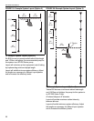
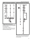
8.1 ROBERTS GORDON
®
System Control
The System Control is an electronic control panel
designed to control CRV-Series heating systems.
The System Control can be used to control an EP-
100 or EP-201 pump from the control panel. Other
pumps such as the EP-301 and 3 Ø models may be
controlled in conjunction with a relay or motor starter.
The System Control can control up to four zones of
burners and up to two vacuum pumps.
The electrical circuit is a 120 Vac (20 A) supply.
The output for the thermostat is 24 Vac.
A System Control operated system has two minutes
post purge pump operation to completely exhaust
products of combustion from the system. A system
control provides indication of power to the pump and
zones and indicates the status of the pressure switch
with lights.
The System Control is ETL listed in accordance with
UL873 – Standard for Temperature Indicating and
Regu lating Equipment.
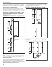
8.2 ROBERTS GORDON
®
ULTRAVAC
™
The ROBERTS GORDON
®
ULTRAVAC
™
is a micro-
processor based control package designed for
modulating control of CRV-Series heaters based on
outdoor temperatures. The controls offer full
modulation between 60% and 100% of system
maximum rated input.
This controller is capable of giving control outputs to
one pump and three heating zones. The controller
also features inputs which are used for indoor and
outdoor signal condition monitoring.
System status and settings are viewed and altered
from a PC (not supplied) running ROBERTS
GORDON
®
ULTRAVAC
™
Software.
ROBERTS GORDON
®
ULTRAVAC
™
Software
requires a PC (not supplied) running Windows
®
95 or
higher, with a Pentium
®
class processor and at least
64k of RAM. For complete installation details, please
refer to the ROBERTS GORDON
®
ULTRAVAC
™
Installation, Operation and Service Manual (P/N
10081601NA), latest revision.
Special design requirements apply for CRV-
Series systems using the ROBERTS GORDON
®
ULTRAVAC
™
Controller.
Buildings today demand all sorts of control options
based on the user’s preference. ULTRAVAC™
controls offer a host of communication options for
integration with controls’ networks to best serve
individual needs:
ULTRAVAC™ BMS Link: Interface ULTRAVAC™
with other building management control platforms
using BACnet
®
or MODBUS
®
protocol which
communicates via our ULTRAVAC™ BMS Link
option.
TCP/IP (LAN): Connect to ULTRAVAC™ via your
local area network of computers. Load ULTRAVAC™
software onto any computer on the network and
control and view your heating system from your
computer via static IP address.
MODEM: Dial into ULTRAVAC™ from anywhere in
the world via modem. Supplied as standard on all
central controllers!
RS-485: Hard wire ULTRAVAC™ directly to your
computer.
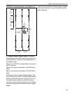
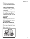
8.3 CORAYVAC
®
Modulating Controls
For a ROBERTS GORDON
®
CORAYVAC
®
Modulating system, combine a modulating
thermostat, a thermostat relay (P/N 90417600K) and
any one of the existing ROBERTS GORDON
®
VFD
assemblies. The result will be a one pump, one zone
DANGER
Electrical Shock Hazard
Disconnect electric before service or
maintenance.
More than one disconnect switch may be
required to disconnect electric to the unit.
Control must be properly grounded to an
electrical source.
Failure to follow these instructions can
result in death or electrical shock.
WARNING
Explosion Hazard
Turn off gas supply to heater before service.
Failure to follow these instructions can result
in death, injury or property damage.