


BLACKHEAT
®
INSTALLATION OPERATION AND SERVICE MANUAL
50 of 74
SECTION 11: VENTING
11.1 General Venting Requirements
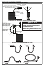
11.1.1 Type C
12
, C
32
& C
62
Appliance
Room Sealed
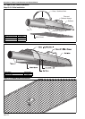
The heaters are designed to be installed as room sealed
appliances. The flue and air intake are run as separate
pipes to the special concentric wall or roof terminal. The
wire mesh inside the fresh air adapter on the heater must
be removed prior to installation. See Page 52, Figure 33.
11.1.2 Type B
22
Appliance
The flue must be fitted with a low resistance terminal. See
Page 52, Figure 33.
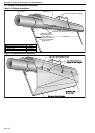
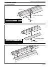
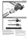
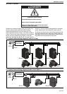
11.1.3 Flue Installation
The fan outlet may discharge vertically or horizontally.
Connection should be made using 100 mm minimum
diameter aluminium or stainless steel flue material to
National Standard and must be adapted to insert into the
100 mm flue adapter. Both fresh air supply and flue duct
shall not exceed 10,000 mm. BH15 and BH20 flue must
be insulated if longer than 5,000 mm. BH25 flue must be
insulated if longer than 8,000 mm. Contact the
manufacturer if more than 2 x 45° offset bends are
necessary. The flue must be self supporting.
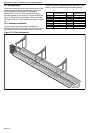
Fans
Horizontal Vertical
83 BWLG 190 x 75 (hole) 150 mm dia.
90 BWLG 190 x 75 (hole) 150 mm dia.
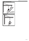
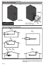
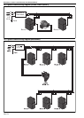
11.1.4 Flueless Installation
If the heater is being installed in an area where
combustion products can be dissipated within the
building, ensure that the fan outlet is horizontal and away
from the burner. Where installation is close to a wall
(perimeter system) or other obstruction close to the fan
outlet or wall angle mounted, install the heater so that the
fan tube is the furthest away from the wall or obstruction,
i.e. the fan will always blow into the building or away from
the obstruction.
11.2 Ventilation Requirements
Detailed recommendations for air supply are given in the
relevant National Standards. There must be an adequate
supply of air for both combustion and general ventilation.
Air vents should have negligible resistance. Do not locate
air vents where they can be easily blocked or flooded, or
adjacent to any flues or extraction systems carrying
flammable vapour.
11.2.1 Flue Installation
Where the heater(s) is flued, the space containing it must
have a permanent outside air vent with a minimum
effective area of 4.5 cm
per kW of heat input. If
mechanical ventilation is employed, the minimum proven
airflow rate shall be 2.35 m/h per kW of heat input.
If the flue is to be horizontally vented through a wall, a
wind-proof terminal must be fitted to outdoor vent pipe to
prevent a back draught.
11.2.2 Flueless Installation (EN 13410)
The installation room must have a volume of at least
10m
3
/kW of installed nominal heat input. A minimum of
10m
3
/h of exhaust air per kW of operating heat input must
be ventilated out of the installation room by either thermal
or mechanical evacuation. Appropriate exhaust and fresh
air openings must be provided and exhaust fans
interlocked with the operation of the heating equipment.
Further no exhaust system is necessary if the building air
change rate is greater than 1.5 per hour or the density of
operating heat input is not greater than 5 W/m
3
.
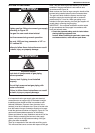
WARNING
Carbon Monoxide Hazard
Multiburner systems are not approved for
unvented use and must be vented outdoors.
Unitary heaters installed unvented must be
interlocked with sufficient building exhaust.
Heaters must be installed according to the
installation manual.
Failure to follow these instructions can result
in death or injury.
WARNING
Cut/Pinch Hazard
Wear protective gear during installation,
operation and service.
Edges are sharp.
Failure to follow these instructions can result
in injury.