


SECTION 13: WIRING
55 of 75
SECTION 13: WIRING
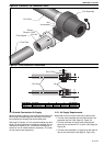
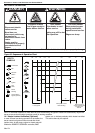
Connect to the electrical supply using a 3 pin plug via a
locally mounted double pole fused switch having a
minimum disconnection of 3 mm on each pole. This
switch should be fused to 3 amps. The burner is fused at
2 amps. There are no control connections in the standard
burner. Control is affected by interruption of the main
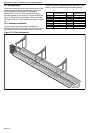
power inlet. See Page 55, Section 13.1 through Page 56,
Section 13.4 for the external wiring details for the single-
burner, double linear and multiburner heater systems.
All wiring must comply with current wiring regulations and
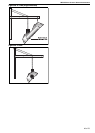
any local regulations which may apply. Always switch off
the supply to the burner and disconnect by removing the
plug before removing the burner side panel.
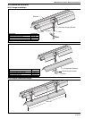
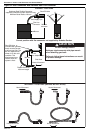
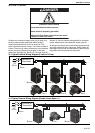
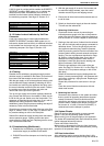
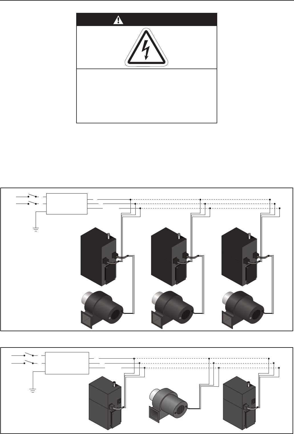
13.1 Typical External Wiring Diagram (Linear or U-Tube)
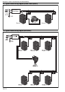
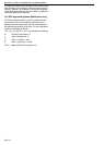
13.2 Typical External Wiring Diagram (Double Linear Option 1)
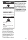
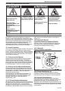
DANGER
Electrical Shock Hazard
Disconnect electric before service.
Heater must be properly grounded.
Failure to follow these instructions can result
in death or electrical shock.
230 V
1 Ø
50 Hz
Burner 1
L
N
Earth
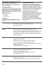
Fan 1
Earth
N
L
Burner 2
Fan 2
Burner 3
Fan 3
Controller or
Thermostat
230 V
1 Ø
50 Hz
Burner 1
Burner 2
L
N
Earth
Earth
N
L
Fan
Controller or
Thermostat