


BLACKHEAT
®
INSTALLATION OPERATION AND SERVICE MANUAL
62 of 74
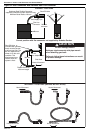
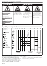
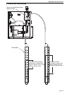
15.2.4 Automatic Flame Control Unit
Remove black ignition lead. Withdraw the connectors.
Remove two screws from the cover. Replace if faulty.
Refit in reverse sequence.
15.2.5 Pressure Switch
Disconnect the two silicone tubes. Remove wires from
the three blades. Remove two screws which secure the
pressure switch to the burner. Remove pressure switch.
Replace pressure switch, if faulty, and refit in reverse
sequence ensuring that the rubber tubes are reconnected
to the switch correctly.
Note: Wires fitted as follows:
NO - Yellow
NC - White
Common - Black
15.2.6 Neons
Remove the two push on connectors and remove the
neons by pushing downwards. Replace in reverse
sequence.
15.3 Maintenance Checklist
Installation Code and Annual Inspections:
All installation and service of ROBERTS GORDON
®
equipment must be performed by a contractor
qualified in the installation and service of equipment
sold and supplied by Roberts-Gordon and conform
to all requirements set forth in the ROBERTS
GORDON
®
manuals and all applicable
governmental authorities pertaining to the
installation, service and operation of the equipment.
To help facilitate optimum performance and safety,
Roberts-Gordon recommends that a qualified
contractor conduct, at a minimum, annual
inspections of your ROBERTS GORDON
®
equipment and perform service where necessary,
using only replacement parts sold and supplied by
Roberts-Gordon.
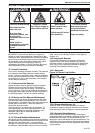
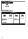
The Vicinity of the Heater Do not store or use flammable objects, liquids or vapours near the heater.
Immediately remove these items if they are present.
See Page 5, Section 3.
Vehicles and Other
Objects
Maintain the clearances to combustibles.
Do not hang anything from, or place anything on, the heater.
Make sure nothing is lodged underneath the reflector, in between the tubes
or in the decorative or protective grilles (included with select models).
Immediately remove objects in violation of the clearances to combustibles.
See Page 5, Section 3.
Reflector Support reflector with hanger and support strap.
Reflector must not touch tube.
Make sure there is no dirt, sagging, cracking or distortion.
Do not operate if there is sagging, cracking or distortion.
Make sure reflectors are correctly overlapped. See Page 23, Section 6.6.1.
or Page 34, Section 7.8.1.
Clean outside surface with a damp cloth.
Vent Pipe Venting must be intact. Using a flashlight, look for obstructions, cracks on
the pipe, gaps in the sealed areas or corrosion.
The area must be free of dirt and dust.
Remove any carbon deposits or scale using a wire brush.
See Page 50, Section 11.
Outside Air Inlet Inlet must be intact. Look for obstructions, cracks on the pipe, gaps in the
sealed areas or corrosion.
The area must be free of dirt and dust. Clean and reinstall as required.