


SECTION 7: VENTING
13 of 51
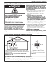
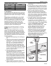
Maximum Vent Lengths Table
7.7 Vent Material
Vent material may be single wall 26 ga. (minimum)
galvanized steel or equal thickness stainless steel.
Completely seal all joints, refer to Page 11, Section
7.2.
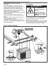
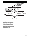
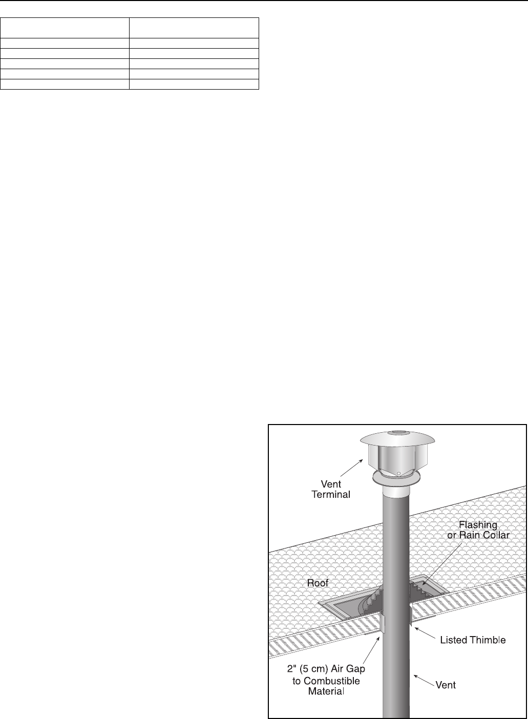
If penetrating a combustible wall or roof, a listed
thimble with 2" (5 cm) clearance must be used.
Where local codes permit, a single section of type
B-1 vent material may be used at the roof or wall
penetration instead of a thimble. Ensure vent
manufacturer's clearance from vent material is
maintained. Seal annular space of the type B-1 vent
as well as all joints in the remaining vent.
7. 8 Replacing an Existing Heater in a Venting
System
When replacing an existing heater in a venting
system, the venting system may not be properly
sized to vent the new heater. The following steps
must be followed with each appliance connected to
the venting system placed in operation, while any
other appliances connected to the venting system
are not in operation.
1. Seal any unu sed openings in the venting sys-
tem.
2. Inspect the venting system for proper size and
horizontal pitch, as required by the NFPA 54/
ANSI Z223.1 - latest revision, National Fuel
Gas Code (US) or Standard CSA B149.1
Natural Gas and Propane Installation Code
(Canada) and these instructions. Determine
that there is no blockage or restriction, leakage,
corrosion and other deficiencies w
hich could
cause an unsafe condition.
3. Close all building doors and windows and all
doors between the space in which the
appliance(s) connected to the venting system
are located and other spaces of the building.
Turn on clothes dryers and any exhaust fans,
such as range hoods and bathroom exhausts
so that they shall operate at maximum speed.
Do not operate a summer exhaust fan. Close
fireplace dampers.
4. Follow the lighting instructions. Place the
appliance being inspected in operation. Adjust
thermostat so that the appliance will operate
continuously.
5. For any appliance having a draft hood, test for
draft hood appliance spillage at the draft hood
relief opening after five minutes of main burner
operation. Use the flame of a match or candle.
6. After it has been determined that each
appliance connected to the venting system
properly vents when tested as outlined above,
return doors, windows, exhaust fans, fireplace
dampers and any other gas-burning appliances
to their previous conditions of use.
7. If improper venting is observed during any of
the above tests, the venting system must be
corrected by a contractor qualified in the
installation and service of gas-fired eq
uipment
or your local gas supplier. If the venting mu st be
resized, use appropriate tables in (US)
Appendix G of NFPA 54/ANSI Z223.1 - latest
revision, National Fu el Gas Code (US) or
Standard CSA B149.1 Natural Gas and
Propane Installation Code (Canada) to
determine minimum size. All vent corrections
must be in accordance with the appropriate
local codes and the NFPA 54/ANSI Z223.1 -
latest revision, National Fuel Gas Code (US) or
Standard CSA B149.1 Natural Gas and
Propane Installation Code (Canada).
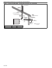
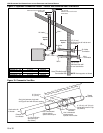
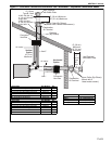
Figure 6: Vent and Roof Detail
Model UHA[X][S]
150 - 400
# of Elbows
40 ft (12.2 m) 1
35 ft (10.7 m) 2
30 ft (9.1 m) 3
25 ft (7.6 m) 4
20 ft (6.1 m) 5