


SECTION 12: USER INSTRUCTIONS
31 of 51
SECTION 12: USER INSTRUCTIONS
The UHA[X][S] Series heaters are fully automatic
and operate from the external controls fitted on site.
12.1 Heater Operation
When the heater has been switched on by the
thermostat installed on site, the main burner will
automatically turn on.
The burner control box will control the safe ignition
of the flame.
All heaters require a constant gas and electricity
supply which must not be interrupted during the
normal operation of this heater.
12.2 Lighting Instructions
12.2.1 To Turn On Heater
1. E n s ure that the electrical and gas supplies to
the heater are on. Check that the on site
controls are "ON".
IMPORTANT: The thermostat setting must be above
the ambient temperature for the heater to operate.
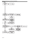
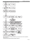
2. The automatic firing sequence will begin as
described on Page 28, Figure 13. The heater
will now operate automatically under the control
of the on site controls.
12.2.2 To Turn the Heater Off
Set the thermostat to the "OFF" position.
The burner will turn off immediately.
The fan will continue to run for 90 seconds.
To restart, turn the thermostat above room
temperatu
re.
12.3 Simple Troubleshooting
Some possible reasons for the heater not operating
are:
1. Ga s s upply not "ON".
2. Electricity supply not "ON".
3. The time and/or temperature controls are not
"ON".
4. A limit switch may have operated. This may be
caused by an interruption of the electrical
supply, failure of the distribution fan or vent or
heat exchanger blockage.
If a temperature limit switch persistently trips, there
is a fault which must be investigated by a contractor
qualified in the installation and service of gas-fired
heating equipment.
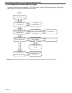
12.3.1 Simple Troubleshooting (Burner Fault)
If the burner fails to ignite for any reason, it will retry
for ignition (four trials total). After four unsuccessful
ignition trials, the control will put the heater into
lockout for one hour.
Lockout should not occur during normal operation of
the heater and indicates there is a fault condition
which must be corrected. There is an LED light on
the ignition control that flashes codes to assist in
fault correction. See Page 31, Figure 15 for LED
indication codes.
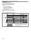
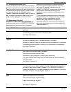
Figure 15: LED Diagnostic Codes
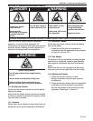
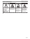
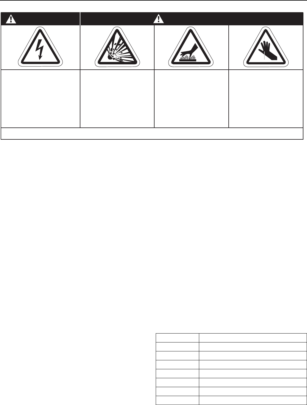
Cut/Pinch Hazard
Wear protective gear
during installation,
operation and service.
Edges are sharp.
WARNING
Failure to follow these instructions can result in death, electric shock, injury or property damage.
Burn Hazard
Allow heater to cool
before service.
Tubing may still be hot
after operation.
Explosion Hazard
Turn off gas supply to
heater before service.
DANGER
Electrical Shock Hazard
Disconnect electric
before service.
Heater must be
connected to a properly
grounded electrical
source.
LED INDICATION FAULT MODE
Slow Flash Normal Operation - No call for heat.
Fast Flash Normal Operation - Call for heat.
2 Flashes Ignition Lockout - No flame detected.
3 Flashes Airflow Fault - Pressure switch open or closed.
4 Flashes Temperature Limit Switch Open
5 Flashes Flame Sense Error - Gas valve not energized.
Steady On Internal Control Failure