


TABLE OF FIGURES
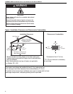
Figure 1: Installation Clearances and Clearances to
Combustibles.............................................................4
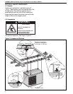
Figure 2: Suspension Methods.................................................6
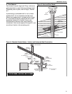
Figure 3: Vent and Roof Detail..................................................9
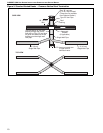
Figure 4: Standard Vented Heater - Vertical and
Horizontal Vent Termination ......................................9
Figure 5: Standard Vented Heater - Common Vertical Vent
Termination.............................................................. 10
Figure 6: Separated Combustion Heater - Vertical and
Horizontal Vent Termination .................................... 11
Figure 7: Concentric Vent Box ................................................ 11
Figure 8: Concentric Vertical and Horizontal Vent
Termination - Separated Combustion Heater........... 12
Figure 9: Gas Connection.......................................................14
Figure 10: Automatic Burner Control Sequence......................20
Figure 11: Gas Valve for Models UHA(S) 150 - 400................20
Figure 12: LED Diagnostic Codes...........................................22