


TABLE OF FIGURES
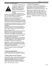
Figure 1: UHA[X][S]150 - 175 Label Placement........................2
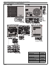
Figure 2: UHA[X][S]200 - 250 Label Placement .......................3
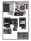
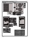
Figure 3: UHA[X][S]300 - 400 Label Placement .......................4
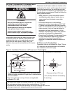
Figure 4: Installation Clearances and Clearances to
Combustibles.............................................................7
Figure 5: Suspension Methods ...............................................10
Figure 6: Vent and Roof Detail................................................13
Figure 7: Standard Vented Heater - Vertical and
Horizontal Vent Termination.....................................14
Figure 8: Standard Vented Heater - Common Vertical Vent
Termination ..............................................................15
Figure 9: Separated Combustion Heater - Vertical and
Horizontal Vent Termination.....................................16
Figure 10: Concentric Vent Box...............................................16
Figure 11: Concentric Vertical and Horizontal Vent
Termination - Separated Combustion Heater .........17
Figure 12: Gas Connection .....................................................20
Figure 13: Automatic Burner Control Sequence......................28
Figure 14: Gas Valve for Models UHA[X][S] 150 - 400............29
Figure 15: LED Diagnostic Codes...........................................31