


24 VA Series Indoor LS Manual
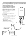
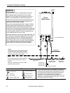
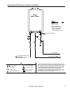
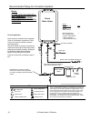
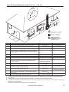
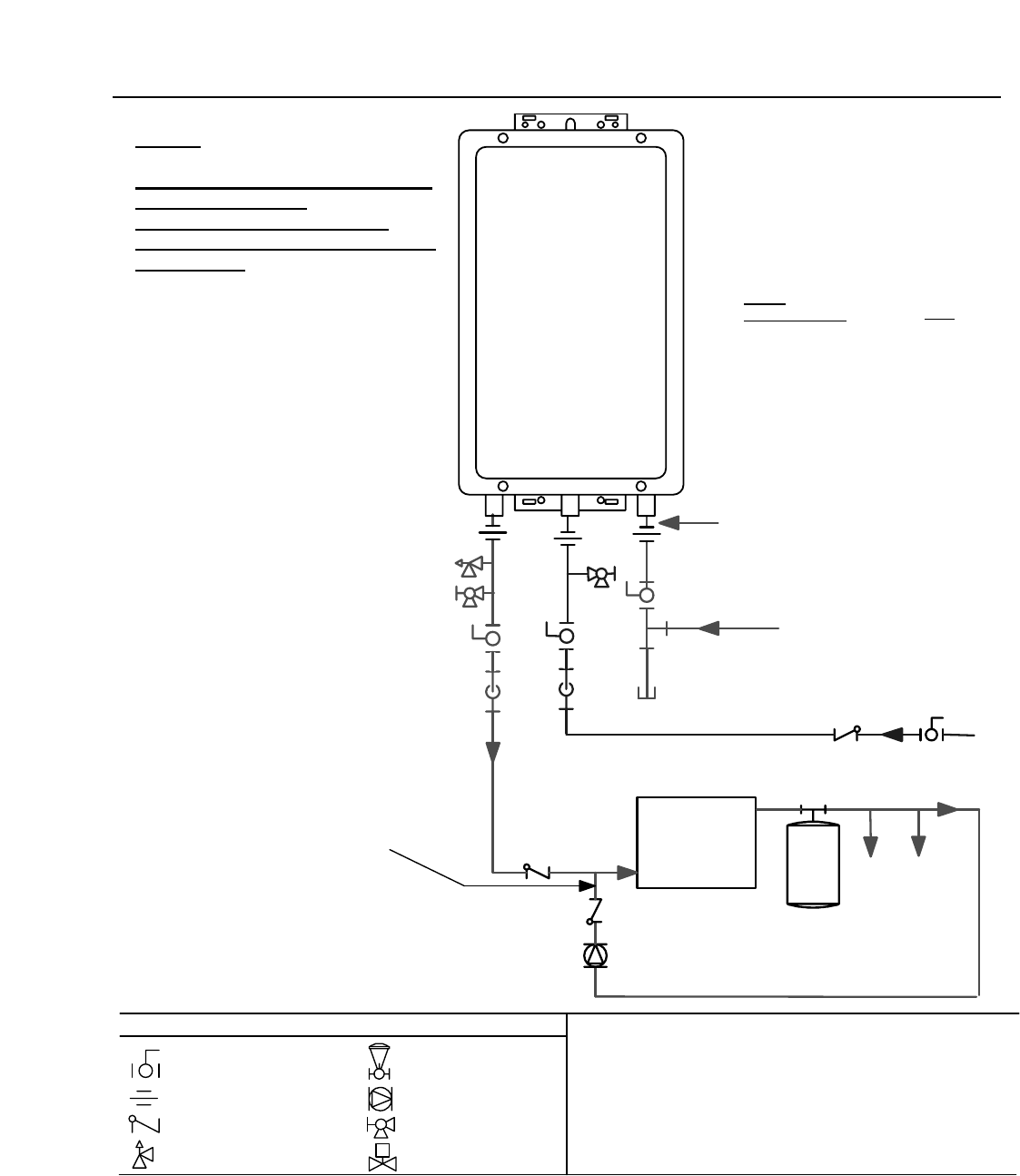
Recommended Piping for Circulation Systems
This is not an engineered drawing, it is intended only as a guideand
not as a replacement for professionally engineered project drawings.
This drawing is not intended to describe a complete system, it is up
to the contractor/engineer to determine the necessary components
for and configuration of the particular system beinginstalled. The
drawing does not imply compliance with local buildingcode
requirements. It isthe engineer/contractor responsiblity to ensure
the installation is in accordance with all local building codes. Confer
with local building officials before installation.
Pressure Relief Valve
3/4" Ball Valve
3/4" Union
Check Valve
S
Pressure Regulator
Circulating Pump
Solenoid Valve
Boiler Drain Valve
KEY
Minimum 3/4" Cold Water Supply Line
Electric Water
Heater
Building
Fixtures
Building Supply
E
x
p
a
n
s
i
o
n
T
a
n
k
G
a
s
S
u
p
p
l
y
QTY
1
1
Rinnai
Water Heater
Notes:
PLEASE NOTE FOR RESIDENTIAL
AND COMMERCIAL
APPLICATIONS, THIS PIPING
ARRANGEMENT MAINTAINSFULL
WARRANTY
Rinnai
Equipment List
Rinnai
Water Heaters
RIK-KIT (Optional)
(3/4" Fittings Include:
2Unions, 2 Ball Valves,
2Drain Valvesand
1Pressure Relief Valve.)
3
/
4
"
G
a
s
C
o
n
n
e
c
t
i
o
n
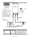
Tank Water Heater to be Sized for
Heat Loss of Circulation Loop.
For this application:
Pump should be controlled by an Aquastat,
Timer or Combination Aquastat and Timer.
Pump to be sized to maintain circulation
loop temperature.
The pump should be sized to overcome the
pressure loss through the tank water heate r,
and supply and return plumbing. Reference
the Rinnai Hot Water System Design
Manual, Pump Sizing for Circulation.
Pump to be of bronze or stainless construc-
tion.
IMPORTANT: Connect the building
return line to the hot water supply line
as close as possible to the Rinnai Water
Heater.