


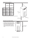

VA Series Outdoor LS Manual 21
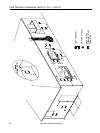
Water Piping
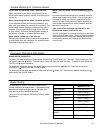
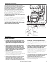
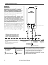
The freeze protection features include electrical heating
elements and intermittent firing of the burner. Freeze
protection may be disabled if electricity or gas is not
supplied, or if there is an error preventing the water
heater from functioning. Loss of freeze protection may
result in water damage from a burst heat exchanger or
water lines.
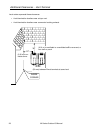
The installation of auto drain down solenoid valves is
optional. However, Rinnai strongly recommends that
these valves be installed to prevent damage from
freezing in case the normal freeze protection should
become disabled. Any product damage due to freezing
will not be covered by the warranty.
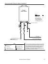
In addition, the solenoid valves should be connected
electrically to a sub-PC board that attaches to the PC
board in the unit. This allows the solenoid valves to
operate if the water heater is disabled due to an error
code.
The solenoid valves and sub-PC board are available for
purchase separately.
Freeze Protection
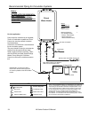
A manual water control valve must be placed in the
water inlet connection to the Rinnai water heater
before it is connected to the water line. Unions may
be used on both the hot and cold water lines for
future servicing and disconnection of the unit.
The piping (including soldering materials) and
components connected to this appliance must be
approved for use in potable water systems.
Purge the water line to remove all debris and air.
Debris will damage the Rinnai water heater.
Toxic chemicals such as those used for boiler water
treatment are not to be introduced to the potable
water used for space heating.
If the appliance will be used as a potable water
source, it must not be connected to a system that
was previously used with a nonpotable water heating
appliance.
Ensure that the water filter on the Rinnai water
heater is clean and installed.
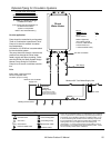
An approved pressure relief valve is required by the
American National Standard (ANSI Z21.10.3) /
Canadian Standard (CSA 4.3) for all water heating
systems.
The relief valve must comply with the standard for
Relief Valves and Automatic Gas Shutoff Devices for
Hot Water Supply Systems ANSI Z21.22 and/or the
standard Temperature, Pressure, Temperature and
Pressure Relief Valves and Vacuum Relief Valves,
CAN1-4.4.
The relief valve must be rated up to 150 psi and to at
least the maximum BTU/hr of the appliance.
The discharge from the pressure relief valve should
be piped to the ground or into a drain system to
prevent exposure or possible burn hazards to
humans or other plant or animal life. Follow local
codes. Water discharged from the relief valve could
cause severe burns instantly, scalds, or death.
The pressure relief valve must be manually operated
once a year to check for correct operation.
The relief valve should be added to the hot water
outlet line according to the manufacturer
,
s
instructions. DO NOT place any other type valve or
shut off device between the relief valve and the water
heater.
Do not plug the relief valve and do not install any
reducing fittings or other restrictions in the relief line.
The relief line should allow for complete drainage of
the valve and the line.
If a relief valve discharges periodically, this may be
due to thermal expansion in a closed water supply
system. Contact the water supplier or local plumbing
inspector on how to correct this situation. Do not
plug the relief valve.
Neither Rinnai nor the American National Standard
(ANSI Z21.10.3) / Canadian Standard (CSA 4.3)
requires a combination temperature and pressure
relief valve for this appliance. However local codes
may require a combination temperature and pressure
relief valve.
Pressure Relief Valve
General Instructions
••
•
•
•
•
•
•
•
•
•
•
•
•
•