


32 VA Series Indoor LS Manual
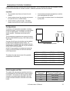
Air Intake Assembly
The air intake system consists of a field supplied 4
inch diameter stainless steel, Schedule 40 PVC, ABS
or CPVC pipe. A maximum 6 feet of semi-rigid
flexible aluminum ducting can also be used. Foil
wrapped dryer vent and cell core products are not
authorized.
The air intake has a zero clearance to combustibles.
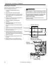
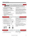
Air Intake Connection
1. Drill 2 small holes at the end of the air intake
pipe.
2. Slide the pipe over the air intake terminal.
3. Using a level, ensure the pipe is straight up and
down.
4. With self tapping screws, attach the pipe to the air
intake terminal.
5. Apply a bead of silicone around the pipe and air
intake terminal, ensuring an air tight connection.
Exhaust Pipe Assembly
Refer to the manufacturer’s installation instructions for
the specific exhaust vent system.
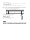
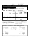
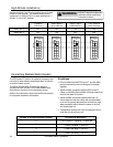
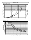
Venting Clearances to Combustibles
Vent Size
Enclosed Unenclosed
Horizontal &
Vertical
Horizontal &
Vertical
4" (102 mm) 4" (102 mm) 1" (26 mm)
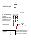
4
3
1
2
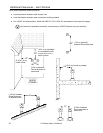
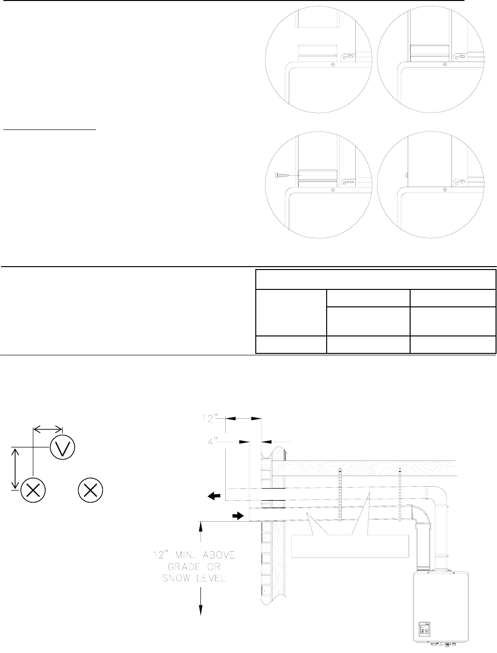
COMBUSTION AIR /
INTAKE
EXHAUST
SLOPE INTAKE AND EXHAUST
TOWARD OUTSIDE TERMINATION
MINIMUM 1/4" PER FOOT
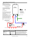
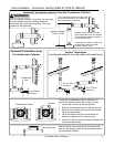
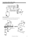
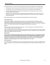
Horizontal Terminations
The air intake must be located in relation to the exhaust as shown below. The air intake must angle 1/4 inch per
foot to the termination to prevent entry of rain.
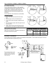
Flue Installation (R98LSi, R98LSi-ASME)
8”
6”
Intake
Optional
Intake
Vent
The vent termination and air
intake must be in the same
pressure zone and face the
same direction.