


21 Boiler Applications Manual 800000026 Rev B
A
4
B
3
C
D
4
2
SCALE
SIZE
DATE
1
SHEET
DWG NO.
REV
A
2 1
D
Approved By
NTS
AA
12/09/09
EL
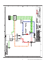
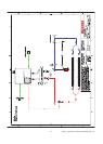
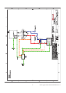
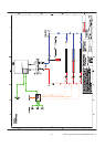
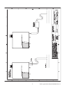
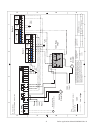
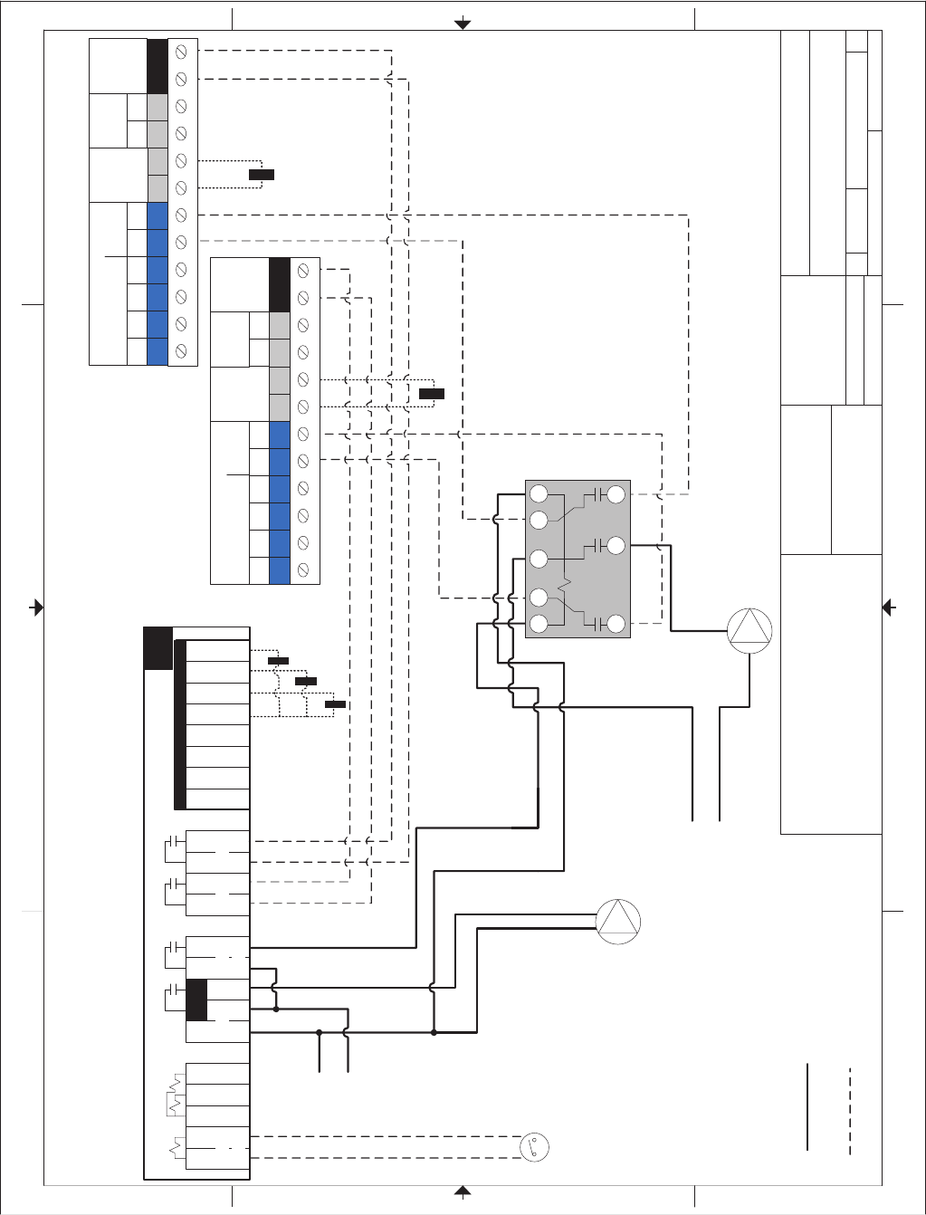
Q Series Boiler
2 boilers with DHW indirect tank
This drawing is the exclusive
property of Rinnai America
Corporation, it may not be
reproduced or given to third
parties.
1 of 1
Rinnai America Corporation
103 International Drive
Peachtree City, GA 30269
1-800-621-9419
Drawn By
JG
Tolerance
Fraction =±
1/16"
x.x=±0.030
x.xx=±0.015
x.xxx=±0.005
This is not an engineering drawing; it is intended only as a guide and not
as a replacement for professional engineering project drawings. This
drawing is not intended to describe a complete system. It is up to the
contractor or engineer to determine the necessary components and
configuration of the particular system to be installed. The drawing does
not imply compliancewith local building coderequirements. It is the
responsibility of the engineer or contractor toensure that the installation is
in accordance with all local building codes. Confer with local building
officials before installation.
3
B
C
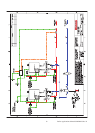
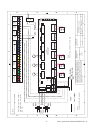
120V
Low voltage
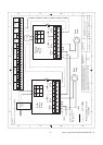
Q Series boilers
2 boilers with DHW indirect tank
1 2 3 4 5 6 9 10 11 12 13 14 15 16 17 18
19
20 21 22
262
Donotapplypower
tN1/
tN2
Com 10K UnO
Sw
Com OutBoilDHW
10A 10A
Stage Stage
1 1 2 2
10A 10A
Power
N L P1
Boil DHW
Pmp/Vlv
Boiler
Demand Dem
Com
DHW
Dem
Setp
Dem
87
Boiler 2
Boiler 1
120V
Input
Heating
Circulator
DHW
Circulator
DHW
Sensor
Outdoor
Sensor
Outdoor
Sensor
120V
Input
Supply
Sensor
Outdoor
Sensor
N
L
Heat Demand From
Thermostat/zone control
N
L
Note:
See 2 boiler with DHW indirect
tank drawing
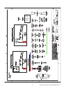
120V Relay
TPST
2
3
6
91
11
8
10
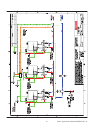
21 22 23
B
12 13
CH
DH
W
14 15 16 17 19 2018
N A
Cylinder connection
Three way valve
DHW
sensor
Outside
Sensor
Bus
Controller
Room
Therm.
On/Off
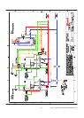
21 22 23
B
12 13
CH
DH
W
14 15 16 17 19 2018
N A
Cylinder connection
Three way valve
DHW
sensor
Outside
Sensor
Bus
Controller
Room
Therm.
On/Off
QEC-09-0001