


For Units 2, 3, 4, and 5:
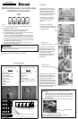
5) Run the 4-pin connector of
Communication Cable B (9.8 ft, 3 m
cable) up through the cable
access in the bottom of
Unit 1’s cabinet.
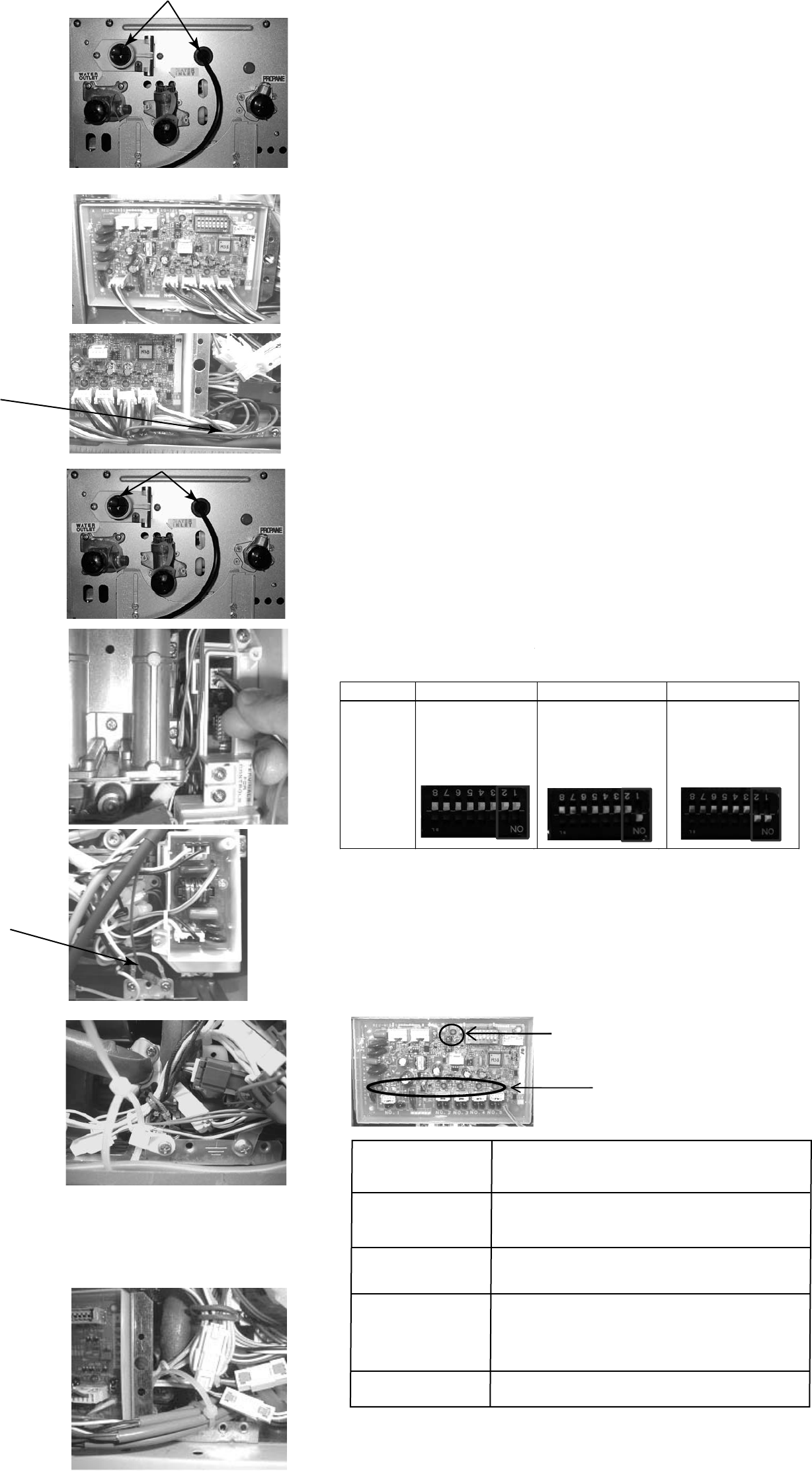
8) Connect the 4-pin connector
from Communication Cable B to the
4-pin socket located at the top of
the water heater control board of
9) Attach the cable tie bracket to
the bottom of the water heater
cabinet using the existing screw.
Pull all of the excess cable up into
Unit 2’s cabinet, and then secure it
tightly to the bracket using the
cable tie.
10) Repeat steps 5 to 9 for Units 3,
4, and 5, as applicable.
Note: Communication Cable B for
Unit 3 plugs into socket 3, Unit 4
plugs into socket 4, etc.
11) After making all of the
connections to the Control Board,
tighten all of the cable ties used to
secure the Communication Cables.
12) Place the front cover panels
back on each of the water heaters
using (4) screws.
13) Restore power to the water
heaters.
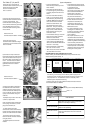
6) Connect the connector of the
Communication Cable B to socket
2 on the Control Board. The
Communication Cable B ground
wire terminals should be grounded
with the MSB ground wire and
Communication Cable A ground
wire terminal.
• The Control Board can
electronically connect up to 25
water heaters.
• When multiple water heaters
are operating, they will attempt
to supply equal amounts of hot
water.
• On initial water ow demand,
from 1 to 3 units which can be
determined by Dip SW setting
of Master MSB board will open
their servos valves until ow
demand is determined. See
Dip SW table for open water
ow valve. Only the necessary
number of water heaters will
begin to re to meet demand.
Water heaters not ring will
close their valves.
• As the default setting, 3 units will
open its servo valve until ow
demand is determined.
• When installation is completed,
do a test run for all units.
• The temperature setting for all
of the connected water heaters
is controlled by the
temperature controller
connected to the water heater
with the Master MSB Board.
Temperature controllers
connected to the other units
will provide maintenance
codes for their respective units.
• If water heaters do not use a
temperature controller, the
temperature setting for the
water heater with the Master
MSB board is used.
• If a water temperature over
140 degree F is desired, then
an MCC-91 controller needs to
be connected to Master
Control Board.
• For proper operation, it is not
recommended that dierent
models be connected together.
• The order in which each water
heater operates is occasionally
rotated to ensure equal usage
among the entire system.
System Operation
7) Run the other end of
Communication Cable B through
the cable access in the bottom of
Unit 2’s cabinet.
Water ow servo valve is open when water
heater is in standby or working.
An error is detected. A temperature controller
must be connected to this unit to read the
error code.
No unit detected at this connection.
Solid
Flashing Slowly (1.2
sec on / 0.5 sec o)
Flashing Quickly
(0.5 sec on / 0.5 sec
o)
O
EXPLANATION
Water ow servo valve is closed when water
heater is not operating.
Unit 2. Communication Cable B
ground wire terminal should be
grounded with the PC board
ground wire.
Indicator lights on the Control Board indicate the status of each
of the water heaters as follows:
LED 1 ~ 5
NOTE: In a recirculation system, in order to increase the tempera-
ture setting, it is necessary to turn off the power supply to the
circulation pump, increase the temperature setting, and then turn
the pump back on. No additional action is necessary when
decreasing the temperature setting.
3 units ready (default) 2 units ready 1 unit ready
Dip SW
setting
No1 OFF
No2 OFF
No1 ON
No2 OFF
No1 ON
No2 ON
LED 1 ~ 5
LED 6
(Working with multiple MSB boards)
Ground wires of
Communication Cable B
Ground wire of
Communication Cable B
• After the test run, check and clean
the water lter on all units.
Combining dierent models may
result in lower performance.
It is recommended that the dip
switch settings on MSB boards
other than the Master MSB board
be set for 1 unit ready.
•
Dip SW table for open water ow servo valve
When viewing the installed MSB board, the dip switch will be as
shown below (upside down).