R×5RL
17
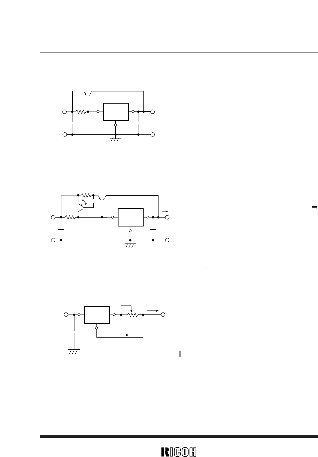
• CURRENT BOOST CIRCUIT
Output current of 60mA or more can be obtained by
the current boost circuit constructed as shown in this cir-
cuit diagram.
• CURRENT BOOST CIRCUIT WITH OVERCURRENT LIMIT CIRCUIT
A circuit for protecting Tr.1 from the destruction
caused by output short-circuit or overcurrent is shown in
this circuit diagram.
When the voltage reduction caused by the current ( aa
I
OUT) which flows through R2 reaches Vbe2 of Tr.2 by
additionally providing the current boost circuit with Tr.2
and R2, Tr.2 is turned ON and the base current of Tr.1 is
increased, so that the output current is limited.
Current limit of Overcurrent Limit Circuit is obtained
as follows :
I
OUT Vbe2/R2
• CURRENT SOURCE
A current source with the structure as shown in this
circuit diagram can be used. Output Current I
OUT is
obtained as follows :
I
OUT
= Vreg /R + ISS
Take care that Output Current IOUT does not exceed
its allowable current.
C2
GND
GND
GND
R
×5RL
SERIES
VOUT
VOUT
C1
VIN
VIN
Tr.1
+
+
C2
GND
GND
GND
R
×5RL
SERIES
VOUT
VOUT
C1
VIN
VIN
Tr.1
Tr.2
R1
R2
I
OUT
Vbe2
+
+
GND
R
×5RL
SERIES
C1
VIN
VIN
R
I
OUT
ISS
VOUT
+
*
1) Vreg : Set Output Voltage of R×5RL Series.
*
1


