7
OPERATION
5. Warning Light / Dirt Sensor
Your power nozzle comes equipped with a
circuit breaker safety system that protects it
from a jammed power nozzle situation.
Common items that cause jammed brushrolls
include socks, excessive threads, corners of
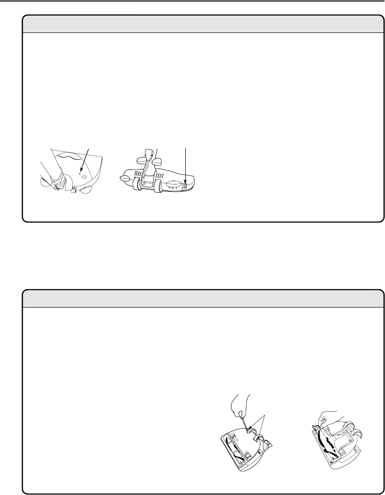
area rugs, etc. The warning indicator light on
top of the unit (see diagram 8) will change from
green to red should this condition occur.
If the circuit breaker trips:
a. Turn off the vacuum cleaner and power nozzle
then unplug the power cord.
b. Remove the object preventing the brushroll
from turning.
c. Locate the circuit breaker switch on the back of
the power nozzle and press it to reset the
breaker (see diagram 9).
d.
When the unit is turned back on, the warning light
should be green and ready to go. If the breaker trips
again, repeat steps a-c again to correct the problem.
If this does not correct the problem, contact
your authorized vacuum cleaner retailer for
further assistance.
6. Dirt Sensor
The warning indicator light will turn orange if
the dirt sensor detects dirt in the carpet and
will change to green when the carpet is clean.
MAINTENANCE AND CARE
1. Removing the Brushroll
IMPORTANT: Before performing any
maintenance work on the power nozzle,
always unplug the vacuum cleaner and
disconnect the wand.
Your brushroll may need to be removed at
times, for example, to cut threads that have
become tangled around the brushroll or to
replace the belt (see "Replacing the Belt").
To remove the brushroll, turn the unit over and
lift off the metal bottom plate by first
unscrewing the two bottom plate screws
located by the rear wheels (see diagram 10).
Pull out the belt cover guard (see diagram 11)
and pull the brushroll out.
To reinstall the brushroll, reinsert the brushroll
back into the unit (make sure the belt is
attached properly). Next, insert the belt cover
guard. Then, place the metal bottom plate
back onto the unit (insert the front end of the
bottom plate first). Re-insert the two bottom
plate screws and secure.
Diagram 8
Warning Light / Dirt Sensor Circuit Breaker Switch
Diagram 9
Bottom
Plate Screws
Diagram 10 Diagram 11


