


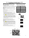

Required adjustment for up to 140°F (60°C) water temperature settings
WARNING: Refer to scald potential warnings on page 4 before
making adjustment. Changing this setting is done at your own risk.
DO NOT alter the #4 DIP Switch if the setting of up to 140°F (60°C) is
not required.
Follow the instructions below if it is determined that a setting of up to
140°F (60°C) is required.
●●
Turn off remote control. Turn off the gas and water shutoff valves.
●
Remove the front cover.
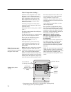
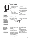
● Find the DIP Switch #4 located at the top left hand side of the PCB.
(See diagram to the right for DIP Switch location).
● Change the DIP Switch #4 setting to the “ON” position. DO NOT alter
any other DIP Switch. The LED on the PCB is flashing. At the same
time, the display of the Main Remote Control starts to flash.
● Press the “SW1” button on the left hand side of the PCB for more than 1
second. The LED on the PCB starts illuminating continuously. At the
same time, the display of the Main Remote Control is on continuously.
● Change the DIP Switch #4 setting back to the “OFF” position. DO NOT
alter any other DIP Switch. The LED on the PCB will stop illuminating.
At the same time, the display of the Main Remote Control will turn off.
● Attach the unit’s front cover.
● Turn on the remote control, gas and water shutoff valves.
● Check and ensure safe operation and performance of the water heater.
See steps below to LIMIT maximum water temperature setting
to 120°F (49°C).
Follow first four bullets points listed above, then continue as listed below:
● Press the “SW2” button on the left hand side of the PCB for more than 1
second. The LED on the PCB starts illuminating continuously. At the
same time, the display of the Main Remote Control is on continuously.
● Change the DIP Switch #4 setting back to the “OFF” position. DO NOT
alter any other DIP Switch. The LED on the PCB will stop flashing.
At the same time, the display of the Main Remote Control will turn off.
● Attach the unit’s front cover.
● Turn on the remote control, gas and water shutoff valves.
● Check and ensure safe operation and performance of the water heater.
!
ON
1
2
3
4
DIP1
ONOFF
1
2
3
4
SW1 SW2
SW3
ON
1
2
3
4
DIP1
DIP1
ON
ON
OFF
OFF
1
2
3
4
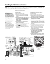
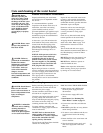
Setting during adjustment
to DIP Switch #4
for temperature.
ON
1
2
3
4
As set from factory
ON
1
2
3
4
ON
1
2
3
4
Setting after adjustment
to DIP Switch #4
for temperature.
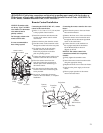
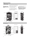
Location of DIP Switches on PC Board.
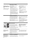
Temperature Setting DIP Switch Adjustment
The content on this page is intended for use by qualified
installation/service personnel ONLY.
ON
1
2
3
4
DIP1
ONOFF
1
2
3
4
SW1 SW2
SW3
“SW2”
Button
“SW1”
Button
LED
DIP
Switches
WARNING: Improper adjustment, alteration,
service or maintenance can cause property damage,
personal injury, or death.
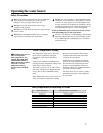
Time/Temperature Relationship in Scalds
DANGER: Hotter water increases
the potential for Hot Water SCALDS.
!
120°F (49°C) More than 5 minutes
125°F (52°C) 1-1/2 to 2 minutes
130°F (54°C) About 30 seconds
135°F (57°C) About 10 seconds
140°F (60°C) Less than 5 seconds
145°F (63°C) Less than 3 seconds
150°F (66°C) About 1-1/2 seconds
155°F (68°C) About 1 second
Table courtesy of Shriners Burn Institute
Water Temperature
Time To Produce a Serious Burn
35