


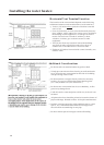

Installing the water heater.
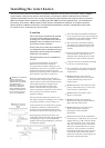
The water heater must be installed with a RTG20002B vent adapter or a UL approved Category III
Stainless Steel equivalent.
The installation of venting must comply
with national codes, local codes, and the
vent manufacturer's instructions
The water heater must be vented to the
outdoors as described in these instructions.
connect this water heater to an
existing Vent or Chimney, it must be
vented separately from all other
appliances.
All vent components (adapters, pipe,
elbows, terminals, etc.) should be UL1738
Certified Stainless Steel Venting Material
(e.g. AL29-4C).
The specified vent termination must be
used. The termination should be a 90°
elbow type with screen. (Refer to page 15)
Use a vent pipe with an anti-disconnection
structure.
The use of a High Temperature Silicone
(500 F) may be required to seal vent
connections. To prevent accidental gas
exhaust leakage, apply a 1/4 wide bead
approximately 1/4 from the end and
another bead against the joint side of the
stop bead.
DO NOT
o
Follow vent manufacturer's installation
instructions.
The unit can be vented either horizontally
or vertically.
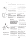
Vent pipe runs must be adequately
supported along both horizontal and
vertical runs.
The maximum recommended unsupported
span should be no more than five (5) feet.
Support isolation hanging bands should be
used. use wire. (See diagram
below).
DO NOT
Venting
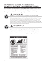
DANGER: Failure to
install the vent adapter and
properly vent the water
heater to the outdoors as
outlined in the Venting
sectionofthismanualwill
result in unsafe operation of
the water heater causing
death, serious injury,
explosion, or fire. To avoid
theriskoffire,explosion,
or asphyxiation from
carbon monoxide, NEVER
operate the water heater
unlessitisproperlyvented
and has adequate air supply
for proper operation as
outlined in the Venting
sectionofthismanual.
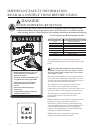
WARNING: Use UL
approved Category III
Stainless Steel vent material
only. No other vent
material is permitted.
WARNING: Refer to
page 7 for clearances to
combustible material.
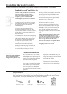
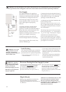
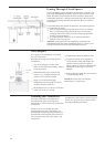
MAXIMUM VENT LENGTH -The
system will not operate if there is
excessive restriction (pressure drop) in the
venting system. Amaximum of 47 feet 6
inches of vent pipe may be used provided
there is only one 90 elbow in the system.
If additional elbows are required: two
elbows can be used with 42 feet 6 inches,
and three elbows can be used with 37 feet
6inchesofventpipe.
A 90 elbow is equivalent to 5 feet to
straight pipe. A45 elbow is equivalent to
2feet6inchesofstraightpipe
The termination elbow does not count as
an elbow when determining total vent
lengths.
o
o
o
.
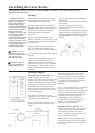
The vent can be installed with a slight
downward slope of 1/4 per foot of
horizontal run toward the vent terminal
(see diagram below). This ensures that
any condensate formed during operation
of the unit is evacuated from the
appliance.
A 1/4 per foot upward slope is acceptable
when it is not possible to vent with a
downward slope, however, a UL approved
Category III Stainless Steel condensate
trap MUST be installed at the beginning
of the horizontal run (See page 15
Typical Horizontal Termination
w/ 1/4 per foot UPWARD Slope or
page 16, Standard Vertical Vent
Termination for examples).
-The
venting may be as short as 12 , provided
one vent termination is installed to the
outdoors through a sidewall, one 90
elbow is included in the installation, and
the wall thimble is installed.
Make sure that the seam of the
vent pipe in horizontal runs is toward the
top of the installation (see illustration to
the far left).
MINIMUM VENT LENGTH
Notice:
o
Venting Lengths
12