


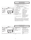

28
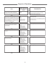
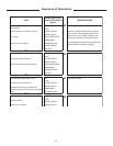
LED Flashing Controlling Function Possible Cause Service Remedy
LINE
Check Breaker Turn breaker ON
Wiring disconnected Check wiring
Does not have 120 VAC Reseat plugs on control
module
24 VAC Transformer wiring problem Repair wiring
Transformer is defective Replace transformer
Does not have 24 VAC Reseat plugs on control
module
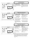
ECO/VENT SWITCH Check connector. Repair wiring
Check connector. Repair wiring
Water in tank too hot
Venting has a problem
Check venting for obstructions
Press reset button and recheck.
PRESSURE SWITCH Combustion air blockage
Combustion air blockage Blower not operating
Air switch stuck open or closed Replace air switch
WATER TEMPERATURE Temp probe wiring is unplugged Check connector or repair wiring
Probe open internally Replace probe
Probe wiring shorted Repair short
or Probe shorted internally Replace probe
no or low water in tank
GAS VALVE Check wire and connection at
burner
Ignition lock out Check and reseat connections
No flame rectification Gas valve shut OFF Turn gas valve ON
Clogged gas valve Replace gas valve
Faulty gas valve Replace gas valve
Defective control Replace control
Gas valve improperly adjusted Adjust gas valve correctly
BLOWER No power to blower Check for power to blower
Power to blower Blower is bad Repair or replace wiring
Replace blower
IGNITOR No power to ignitor Check for power to ignitor
Power to ignitor Ignitor is bad Repair or replace wiring
Replace ignitor
CONTROL HEALTH System problem on circuit board
System board OK
Polarity is reversed Correct polarity
Poor or incomplete ground
Proper ground and polarity
Ensure adequate grounding to unit
and in electrical circuit
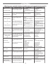
GREEN LED ON MAIN
CONTROL BOARD
Monitors polarity and ground circuit.
ON when ground and polarity are
OK.
Attempts to fire for 4-6 seconds; then
Ignitor current draw is too low.
See i
g
nitor lockout on
p
a
g
e17
Press red reset button. If error
occurs repeatedly, replace main
control board
Monitors ignitor element output. ON
when
p
ower is a
pp
lied to the i
g
nitor
Monitors the controllers hardware
(circuit boards) and software. ON
when controller is functionin
g
OK
Broken or corroded burner ground
wire
Connectors on controlled panel
un
p
lu
gg
ed
Unit will make three (3) successive
trials; then lock out.
Monitors the blower motor output.
ON when power is applied to the
blower.
Monitors water temperature inside
the tank (Thermostat). ON when the
water temp drops below set point
(
tem
p
erature settin
g)
.
Something is wrong with the
tem
p
erature
p
robe
Monitors the gas valve output. ON
when power is applied to the gas
valve
or
Monitors the air pressure switch. ON
when the
p
ressure switch is closed.
Means there is sufficient combustion
airflow.
Check intake and exhaust piping
and flue for obstructions
Check and repair blower wiring;
re
p
lace blower motor
Normal when water gets too hot.
Cool tank. Determine cause for
over tem
p
erature.
Monitors water temperature in the
tank and exhaust vent temperature.
To diagnose, must determine which
function is at fault.
Vent switch overtemp switch is
open
No or not enough water in tank.
Check orifices to insure they match
fuel type.
Water in tank is too hot (ECO is
activated). Check water temp in
tank on display board
Monitors incoming AC line voltage.
ON when line volta
g
e is
p
resent.
Plugs on module disconnected or
loose
Monitors incoming voltage from the
transformer. ON when secondary 24
VAC is present.
Monitors the ECO switch. ON when
ECO switch is closed (normal
p
osition
)
.
Water temp probe unplugged or
dama
g
ed
Vent temp probe unplugged or
dama
g
ed
or
Water in tank too low
Make sure tank is full of water.
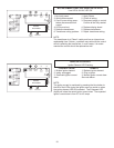
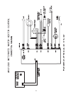
Display Board LEDs
What they mean, controller functions, possible causes and suggested service remedies.