


15
NOTES
________________________________________________________________________________
________________________________________________________________________________
________________________________________________________________________________
________________________________________________________________________________
________________________________________________________________________________
________________________________________________________________________________
________________________________________________________________________________
________________________________________________________________________________
________________________________________________________________________________
________________________________________________________________________________
________________________________________________________________________________
________________________________________________________________________________
________________________________________________________________________________
________________________________________________________________________________
________________________________________________________________________________
________________________________________________________________________________
________________________________________________________________________________
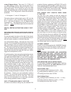
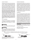
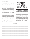
GAS VALVE ADJUSTMENT
Let the unit start to cycle and listen carefully to the igni-
tion. If the ignition was quiet, the valve will need no
adjustment. If it was a loud ignition, the unit rumbles, or
there was no ignition at all, follow these steps:
IF THERE WAS NO IGNITION:
1. Make sure the gas valve is in the "on" position, gas is
on to the unit, and the gas valve wiring harness is
plugged into the gas valve and into the control board.
2. Turn the adjustment screw under the brass cap. Turn
one full turn clockwise with a small flathead screwdriver.
Turning the adjustment screw clockwise increases the
amount of gas.
3. If the unit still does not ignite, turn the adjustment
screw two full turns counterclockwise.
IF IGNITION WAS POOR:
1. Look at the color of the flame through the sight glass
while the unit is running. If it is green or red in color, or
the heater whistles on ignition, turn the adjustment screw
counterclockwise at 1/8” turn intervals until the flame
turns blue/light blue in color or the whistling at ignition
stops. If the flame is very weak or pulsing, turn the
adjustment screw clockwise until the flame steadies.
2. Put the gas valve adjustment screw cover back in
place and tighten.
3. Put the AdvantagePlus cabinet door back into place.
THERE ARE NO USER SERVICEABLE PARTS WITH-
IN THE CONTROL SYSTEM. TO MAINTAIN SAFETY
AND PROPER APPLIANCE PERFORMANCE, REFER
ALL TROUBLESHOOTING TO QUALIFIED SERVICE
PERSONNEL.
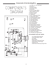
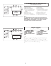
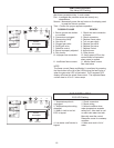
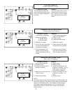
TROUBLESHOOTING
The appliance controller has many inherent diagnostic
and fault detection routines built into its operating soft-
ware and hardware. These routines, along with the three
digit LED display and nine LED status indicators present
on the display panel, can greatly assist the service per-
son in quickly pinpointing the source of problems that
may occur with the appliance. In certain circumstances,
multiple LED's may be lit or flashing to better pinpoint the
problem. The following charts, diagrams, and informa-
tion can be used during troubleshooting procedures. See
also Trouble Shooting Guides and Sequence of
Operations at the end of this Use and Care Manual.
ON
OFF
M
P
C
1
3
2
PILOT ADJ
SEE SIDE WARNING
LABEL
PRESS
MAX
1/2
PSI
WR
W
R
CAUTION
!
Gas Valve
Adjustment
Screw