COMMISSIONING
38
Commissioning the Solar Circuit
To commission and check the solar circuit:
1. Switch off the electrical supply at the power outlet to
the solar storage tank.
If the pump has been operating, wait five minutes to
allow the drain back of the closed circuit fluid in the
solar circuit.
2. Remove the pipe cover from below the gas booster
and the lower and upper front covers from the solar
storage tank.
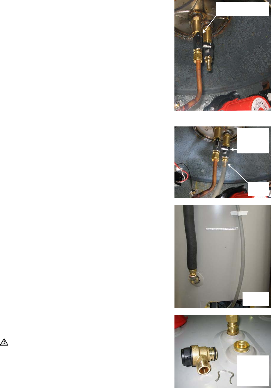
3. Ensure the isolation valve in the pipe work between
the outlet of the heat exchanger and the solar pump,
located behind the lower front cover of the solar
storage tank, is fully open.
Attach Closed Circuit Fluid Level Hose
4. Attach the clear hose to the solar circuit.
To attach the hose:
Ensure the heat exchanger drain valve is closed.
The heat exchanger drain valve is located
adjacent to the solar pump, behind the lower front
cover of the solar storage tank.
Attach one end of the hose to the hose tail
connection.
It may be necessary to secure the hose with a
hose clamp.
Plug the free end of the hose.
Affix the hose securely in a vertical orientation to
the front of the solar storage tank using tape,
adjacent to the text, “MINIMUM FLUID LEVEL
WITH PUMP OPERATING”.
5. Disconnect the drain line from the solar circuit relief
valve at the top of the solar storage tank. Remove the
spring clip from the solar circuit relief valve and
remove the valve.
Warning: The solar circuit may be under
pressure. Take care when removing the solar circuit
relief valve, as a sudden discharge of pressurised hot
air may be experienced. This discharge will create a
sharp sound of air being released.
heat exchanger
isolation valve open
attach
hose
heat
exchanger
drain valve
closed
affix hose
to tank
disconnect
drain line
and remove
solar circuit
relief valve


