


Additional Construction Features:
ELECTRICAL CONNECTIONS – Prewired,
accessible control box with multiple knock-outs on top
and side in size selections to match the Canadian
Electrical Code. Sizes range from 1/2" to 2".
A grounding screw is provided for attaching an
equipment grounding conductor.
STANDARD EQUIPMENT ASME T&P
VALVE –
This is a double safety valve that relieves
when temperature or pressure becomes excessive.
AUTOMATIC TEMPERATURE CONTROL –
Water temperature settings from OFF and ranging from
90°F up to 180°F (32°C to 82°C) are maintained by
immersion thermostat that insures instant shut off at
the selected temperature for safety and economy of
operation. One thermostat is supplied as standard. For
element steps, up to two additional thermostats can
be supplied – see optional controls. Over temperature
protection is provided by an immersed high temperature
limit control, factory set at 200°F (93°C).
MAGNETIC CONTACTORS – All models
equipped with contactors, factory wired for simplicity of
installation and economical maintenance throughout life
of the unit.
240 VOLT CONTROL CIRCUIT – all units are
furnished with a 240 volt control circuit. All controls
(thermostats, high temperature limit, etc.) are operated
off of this basic 240 volt control circuit.
Optional Equipment:
ELEMENT FUSING – In addition to all the above
construction features, on immersion thermostat models
9 KW through 54 KW there is internal fusing available
that protects all elements, magnetic contactors,
thermostats and internal wiring circuits. On immersion
thermostat models 24 KW and above, additional
thermostats are provided so that the maximum element
input will not exceed 18 KW per step. Temperature
differential between steps can be set as desired. On 24
through 36 KW units, two thermostats are provided and
on the 45 and 54 KW units, three thermostats are
provided.
For optional fusing, suffix “F” should be added to the
model number. Ex. EG120CF-45KW.
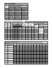
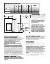
DIMENSIONAL INFORMATION
All dimensions shown in English and Metric
MODEL
APPROX.
SHIPPING
NUMBER UNITS
A BCDE
WEIGHT (LBS.)
EG50
inches 43-5/8 26-1/4 36-1/4 32 17-1/4 270 lbs.
mm 1108 667 920 813 438 122 kgs.
EG85
inches 57-11/16 28-1/4 49-1/2 34 18-1/4 350 lbs.
mm 1465 718 1258 864 464 159 kgs.
EG120
inches 67-5/8 30-1/4 58-3/4 36 19-1/4 430 lbs.
mm 1718 768 1493 914 489 185 kgs.
B
D
E
A
4
3
/
4
"
(121mm)
36
1
/
8
"
(917mm)
3
/
4
"
T&P
5"
(127mm)
SYSTEM SENTINEL
AUTOMATIC
TEMPERATURE
CONTROL
(IMMERSION ONLY)
1
1
/
2
"
COLD INLET
NIPPLE
1
1
/
2
"
HOT OUTLET
NIPPLE
C
SYSTEM SENTINEL
™
– All models
employ a diagnostic panel utilizing light
emitting diodes (L.E.D.), corresponding
to the number and location of each
heating element. L.E.D.’s are energized
when the electric elements are operat-
ing. An unlit L.E.D. pinpoints the exact
location of a non-functioning element,
making element operation diagnosis
simple and positive.
The minimum distance to provide
adequate clearance for protection of
combustible material is 0 inches from
jacket and 18 inches from access door.
However, additional clearance for
accessibility to permit inspection and
servicing such as removing heating
elements or checking controls must be
provided. All models are approved for
installation on combustible flooring.