


WHY PUMP TANKS ARE IMPORTANT
A pump tank is an essential part of any well system, delivering
these benefits:
n
It ensures that your pump will run for at least one minute
each time it cycles, as required by pump manufacturers.
n
It stores a supplemental water supply between pump cycles,
to reduce the number of cycles throughout the day, and
helps prolong pump life.
n
It helps maintain water pressure within your system, ensuring
proper operation of your dishwasher and washing machine,
and robust flow for showering and bathing.
A properly sized pump and pump tank will work as a team to meet
your needs and will deliver many years of dependable service.
HOW TO SIZE A PUMP TANK
1.If you know your current pump size, use columns 2 and 3 in the
sizing chart to make your tank selection.
2.If you do not know your pump size or the size of your current
tank, count all your water fixtures. Be sure to include sinks,
tubs, showerheads, outside faucets, utility sinks, dishwasher,
washing machine, etc. Count each fixture individually. Use
columns 1 and 3 in the size chart to make your tank selection.
3.If replacing a glass-lined or other “standard” tank with a
diaphragm tank, use columns 3 and 4 in the size chart to
make your tank selection.
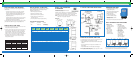
HOW A DIAPHRAGM PUMP TANK WORKS
1
28psi 35psi 50psi 35psi
35psi 50psi 35psi
234
HOW TO INSTALL A PUMP TANK
Each STA-CHARGED Pressurized Diaphragm Tank includes a
detailed, manual that takes you step-by-step through
installation procedures such as:
1. Determining proper tank location.
2. Attaching the acceptance fittings.
3. Adjusting the tank pre-charge pressure.
4. Leveling the tank and connecting it to
the water supply line.
5. Fine-tuning the tank to assure lag-free delivery.
TOOLS NEEDED FOR INSTALLATION
n
Screwdriver
n
Pipe Wrench
n
Hacksaw
n
Pliers
n
Teflon Tape
n
Pressure Gauge
(Tire Gauge)
SIZING CHART
1234
NUMBER OF ESTIMATED DIAPHRAGM “STANDARD”
WATER FIXTURES PUMP SIZE TANK MODELS TANK SIZES
UP TO 7 5-7 GPM* PMD-20, PMDH-20 42 GALLON
8-12 10 GPM* PMD-45 82 GALLON
13-16 12-15 GPM* PMD-65 120 GALLON
17-28 20 GPM* PMD-85,PMD-119 220 GALLON
*GPM = Gallons Per Minute
MODEL, ITEM, DIMENSIONS
& DRAWDOWN
Drawdown is the actual useable water a tank
can deliver during a cycle.
Drawdown will vary depending on the operating pressure range
set for your pump tank. Drawdown is a function of the tank volume.
Approximately 1/3rd of the tank total volume is usable water.
NOTE: The maximum working pressure is 100 PSI. Install a pressure
relief valve on every pump installation.
HORIZONTAL
A TYPICAL PUMP TANK INSTALLATION
REPLACING AN EXISTING PUMP TANK
A standard pump tank can be replaced with a diaphragm tank. This
will ensure operation of a maintenance-free system.
n
Install a pressure relief valve at the tank connection to ensure system
protection.
n
Be sure to plug the air port on a jet pump, since outside air is no
longer needed.
n
All open bleeder orafaces in the well casing must be plugged.
NOTE: A pressurized tank always takes up less space than a similar
capacity standard pump tank.
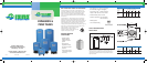
DIAPHRAGM PUMP TANKS
n
For dependable protection of your jet
or submersible well pump
n
Steel shell with powder-coated exterior
for maximum corrosion resistance
n
Metal air charge valve
is conveniently located and
resistant to mechanical damage
n
Strong butyl diaphragm delivers
dependable service
n
Epoxy-coated inner shell protects the water reservoir
IN-LINE
FREE STANDING
MODEL
VOL.
US GAL
DRAWDOWN
30-50 PSI
CONN SIZE
NPT
INCHES
A
INCHES
B
INCHES
C
INCHES
SHIPPING
WEIGHT
LBS
FREE STANDING PUMP TANKS
PMD-14 14 4.3 1 F 24 2 15 3/8 24
PMD-20 20 6.2 1 F 31 2 15 3/8 34
PMD-26 26 8.1 1 F 38 1/2 2 15 3/8 40
PMD-32 32 9.9 1 F 46 2 15 3/8 52
PMD-45 45 13.9 1 1/4 F 35 1/2 2 22 65
PMD-65 65 20.1 1 1/4 F 47 1/2 2 22 90
PMD-85 85 26.7 1 1/4 F 60 1/8 2 22 114
PMD-119 119 37.0 1 1/4 F 61 2 26 161
IN-LINE PUMP TANKS
PMDI-2 2 .6 3/4 M 12 1/2 – 8 3/8 4.5
PMDI-5 4.6 1.4 3/4 M 14 3/4 – 11 3/8 7.5
PMDI-7 7 2.3 3/4 M 18 7/8 – 11 3/8 11
PMDI-14 14 4.3 1 M 24 2 15 3/8 24
HORIZONTAL PUMP TANKS
PMDH-7 7 2.3 3/4 M 18 7/8 – 11 3/8 11
PMDH-14 14 4.3 1 M 20 – 15 3/8 24
PMDH-20 20 6.2 1 M 28 – 15 3/8 34
We also offer glass-lined tanks up to 120 gallons and galvanized tanks
up to 900 gallons. Please call 1-800-365-4054 for more information.
1. START-UP CYCLE
Diaphragm is pressed
against the bottom of
the chamber.
2. FILL CYCLE
Water is pumped
into the reservoir,
which forces the
diaphragm upward
into the air chamber.
3. HOLD CYCLE
Pump-cutoff pressure
is attained. Diaphragm
reaches its upmost position.
Reservoir is now filled to its
rated capacity.
4. DELIVERY CYCLE
Pump remains shut
off while air pressure
in top chamber
forces diaphragm
downward, delivering
water to the system.
186750_RPMCP00107 11/6/07 9:02 AM Page 6