


12
Regency
®
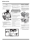
CLASSIC C33-3 Freestanding Gas Stove
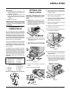
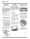
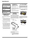
Diagram 2
LOG SET
INSTALLATION
WARNING: Dangerous operating condi-
tions may occur if these logs are not po-
sitioned in their approved locations. Read
the instructions below carefully and refer
to the diagrams. If logs are broken do not
use the unit until they are replaced. Broken
logs can interfere with the pilot and burner
operation.
The gas log kit contains the following:
a) Front Log
b) Rear Log
c) Small Cross Logs (2)
d) Bag of embers
e) Bag of rock wool
1) Remove the logs from the box and carefully
unwrap them. The logs are fragile, handle
with care. Do not force into position.
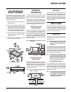
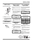
2) Place the rear defl ector on the rear log
support pins in the back of the unit.
3) Place the rear log into the rear of the fi re-
box, aligning the holes on the underside of
the log with the rear log support pins and
carefully push the log down onto the pins.
See diagrams 1 and 2.
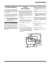
4) Ensure the front defl ector is over front log
pins. See diagram 1.
5) Place the front log in the front of the unit,
aligning the holes on the underside of the
log with the log support pins in the front of
the unit. Carefully push the log down onto
the pins. See diagram 1.
Diagram 1
TEST FOR
FLUE SPILLAGE
This heater must be properly connected to a
venting system.
WARNING: Operation of this heater
when not connected to a properly
installed and maintained venting
system or tampering with the vent
safety shutoff system can result in
carbon monoxide (CO) poisoning
and possible death.
A “spillage” test must be made before the in-
stalled unit is left with the customer. Follow the
procedure below:
1) Start all exhaust fans in the home and then
close all doors and windows in the room.
2) Light the unit and set controls to maxi-
mum.
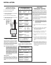
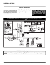
3) After fi ve minutes, test that there is a “pull” on
the fl ue by placing a smoke match, cigarette
or similar device which gives off smoke, on
the edge of the draft hood. See Diagram
below.
The smoke should be drawn into the draft hood.
If the smoke is still not drawn into the draft hood,
turn the unit off and check for the cause of the
lack of draft. If necessary, seek expert advice.
Note: If the fl ue is blocked or has a strong
reverse fl ow, the thermally actuated
safety switch mounted in the draft
hood will automatically shut off the
gas supply in less than 10 minutes.
If the heater turns off because of this
during the spillage test, check for
the cause of the lack of draft and if
necessary, seek expert advice.
To reset the thermally actuated safety switch,
let the unit cool for 10 minutes, then press the
red reset button on the back of the switch. See
Diagram below.
6) Place the cross logs on top of the larger
logs aligning the holes on the underside of
the cross log with the log pins in the larger
logs. See diagrams 1 & 2. Carefully push
the cross logs onto the pins.
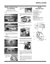
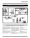
7) Distribute the embers along the mesh em-
ber tray, but do not cover the burner ports.
(Burner ports are the little holes on the top of
the burner tube.) Pull off ember size pieces
from the rock wool. Gently place the pieces
on top of the embers. See diagram 3.
Do not put the rock wool directly on the
burner. Close the door and turn the unit on
as per lighting instructions. Watch the fl ame
to see if it fl ows smoothly around from one
end to the other. (Use Extreme Caution and
ensure proper light off of burner.)
8) If the fl ame hesitates at any point, check
the area of hesitation and see if there is an
ember or rock wool blocking a burner port or
ports. If so, move the obstruction and then
check the fl ame fl ow again.
Diagram 3
INSTALLATION