


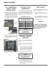

20 U32-3 FPI Direct Vent Gas Insert
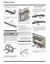
OPTIONAL REMOTE
CONTROL
Use the FPI Remote Control Kit approved for
this unit. Use of other systems may void your
warranty.
The remote control kit comes with a hand held
transmitter, a receiver and a wall mounting
plate.
1) Choose a convenient location on the wall
to install the receiver and the receptacle
box (protection from extreme heat is very
important). Run wires from the fireplace to
that location. Use Thermostat Wire Table.
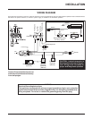
2) Connect the wires as per the wiring dia-
grams below.
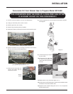
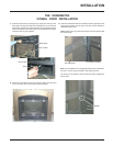
FINAL CHECK
Before leaving this unit with the customer, the
installer must ensure that the appliance is firing
correctly. This includes:
1) Clocking the appliance to ensure the cor-
rect firing rate (rate noted on label) at 15
minutes.
2) If required, adjusting the primary air to
ensure that the flame does not carbon. First
allow the unit to burn for 15 min. to stabilize.
3) Check for proper draft.
CAUTION
Any alteration to the product that
causes sooting or carboning that
results in damage to the exterior
facia is not the responsibility of
the manufacturer.
CAUTION
Do not connect the millivolt
remote control wires for
to the 120V wires.
3) Install 3 AAA alkaline batteries in transmit-
ter and 4 AA alkaline batteries in the
receiver. Install the receiver and its cover
in the wall. Switch the remote receiver to
"remote" mode. The remote control is now
ready for operation.
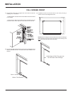
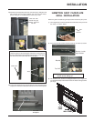
OPTIONAL WALL
THERMOSTAT
A wall thermostat may be installed if desired,
follow the wiring diagram below. FPI offers an
optional programmable thermostat but any 250-
750 millivolt rated non-anticipator type thermo-
stat that is CSA, ULC or UL approved may be
used.
14 GA.
16 GA.
18 GA.
20 GA.
22 GA.
50 Ft.
32 Ft.
20 Ft.
12 Ft.
9 Ft.
Recommended Maximum Lead Length
(Two-Wire) When Using Wall
Thermostat (CP-2 System)
Wire Size Max. Length
Thermostat Wire Table
CAUTION
Do not connect the millivolt wall
thermostat wires
to the 120V wires.
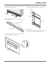
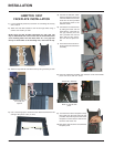
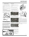
2) Mount the 3-panel Screen Door / Frame
Assembly to the flange on Sub-Frame,
ensuring to line-up holes. Secure using the
4 screws provided.
THE KENSINGTON
3-PANEL DOOR
INSTALLATION
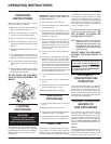
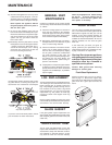
Sub-Frame
1) Install the Sub-Frame by hooking the top
flange onto the top of the Glass Door and
swing the Sub-Frame towards the unit. Pull
out the hooks which already secure the
Glass Door and place them thru the holes
in the bottom of the Sub-Frame to secure
both the Glass Door and Sub-Frame in
place together.
Glass Door
Sub-Frame
Hook
INSTALLATION