


Clearances
Unless otherwise stated the clearances listed below are Minimum
distances to combustible materials. Please Note: A major cause
of chimney related fi res is due to a failure to maintain required
clearances (air space) to combustible materials. It is of the greatest
importance that this fi replace and vent system be installed only in
accordance with these instructions.
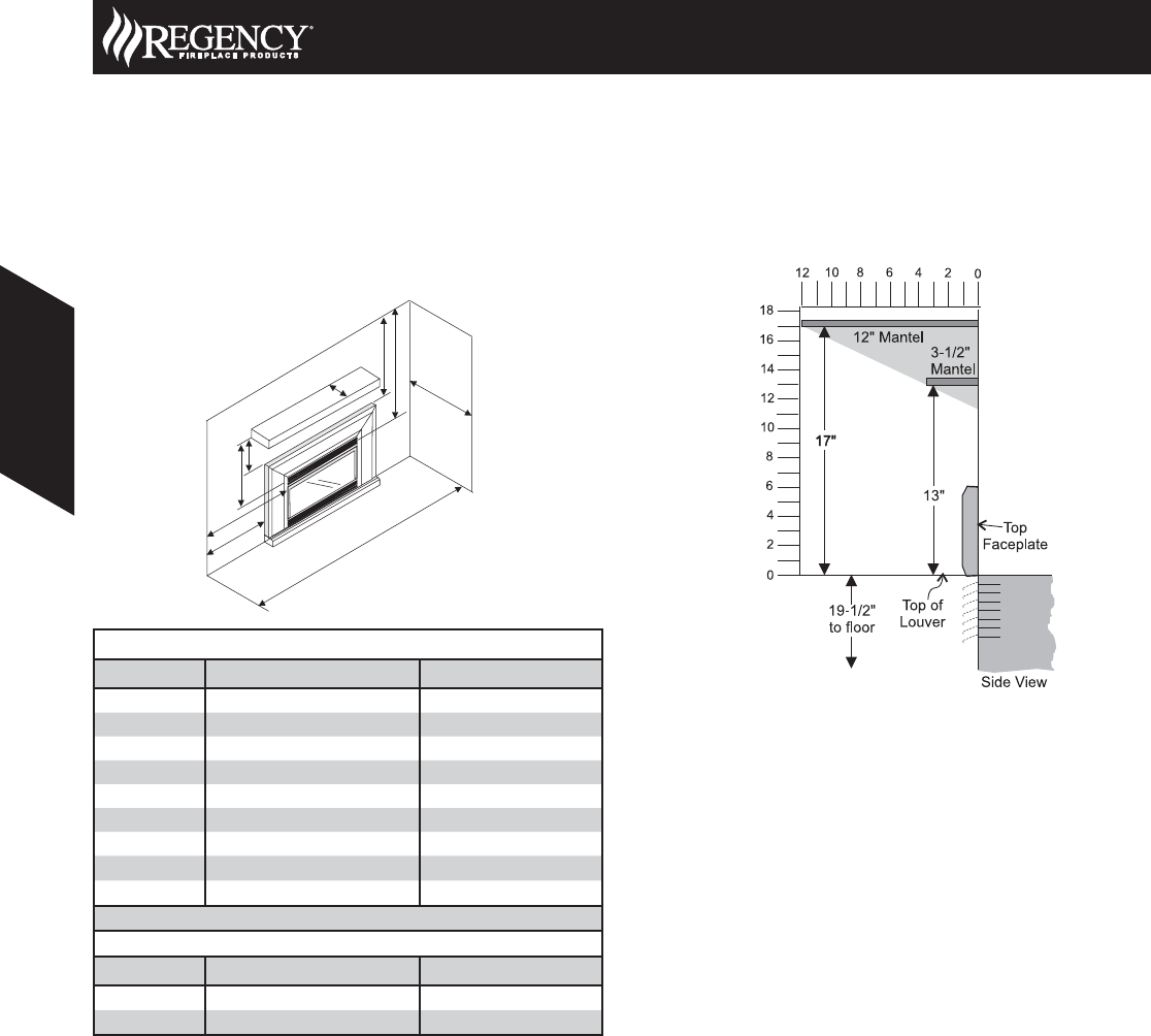
Combustible Mantels
Because of the extreme heat this fi replace emits, the mantel
clearances are critical. Combustible mantel clearances from top of
the louvers are shown in the diagram below. Mantel may be installed
anywhere in the shaded area or higher.
Note: A non-combustible mantel may be installed at a lower
height.
Note: Ensure the paint that is used on the mantel and the facing
is “heat resistant” or the paint may discolour.
G
H
I
A
D
B
E
F
C
Clearances to Combustibles
Dimension Description U31
A From Unit to Sides 10” (254mm)
B From Unit to Ceiling 47-1/2” (1207mm)
C From Unit to Mantel see mantel clearances
D From Standard Surround to Sides 4” (102mm)
E From Standard Surround to Ceiling 41-1/2” (1054mm)
F Minimum Mantel Height 13” (330mm)
G Maximum Mantel Depth 12” (305mm)
H Minimum Alcove Width 48” (1219mm)
I Maximum Alcove Depth 36” (914mm)
*No Hearth Required
Clearances when installed with a Zero Clearance Kit
Dimension Description U31
F Minimum Mantel Height 20” (508mm)
G Maximum Mantel Depth 11-1/2” (292mm)
NOTE: Mantel clearances for Installation into a Zero Clearance Kit
are different. Please refer to the Zero Clearance Kit Manual
for details.
U31 Regency Gas Insert
120 August 2008 Product Specifi cations Book
Gas Inserts
Gas Inserts