


Regency
®
P121-2/P121LC-2/P121RC-2/P131-2 Zero Clearance Direct Vent Gas Fireplace
32
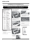
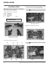
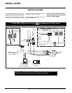
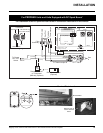
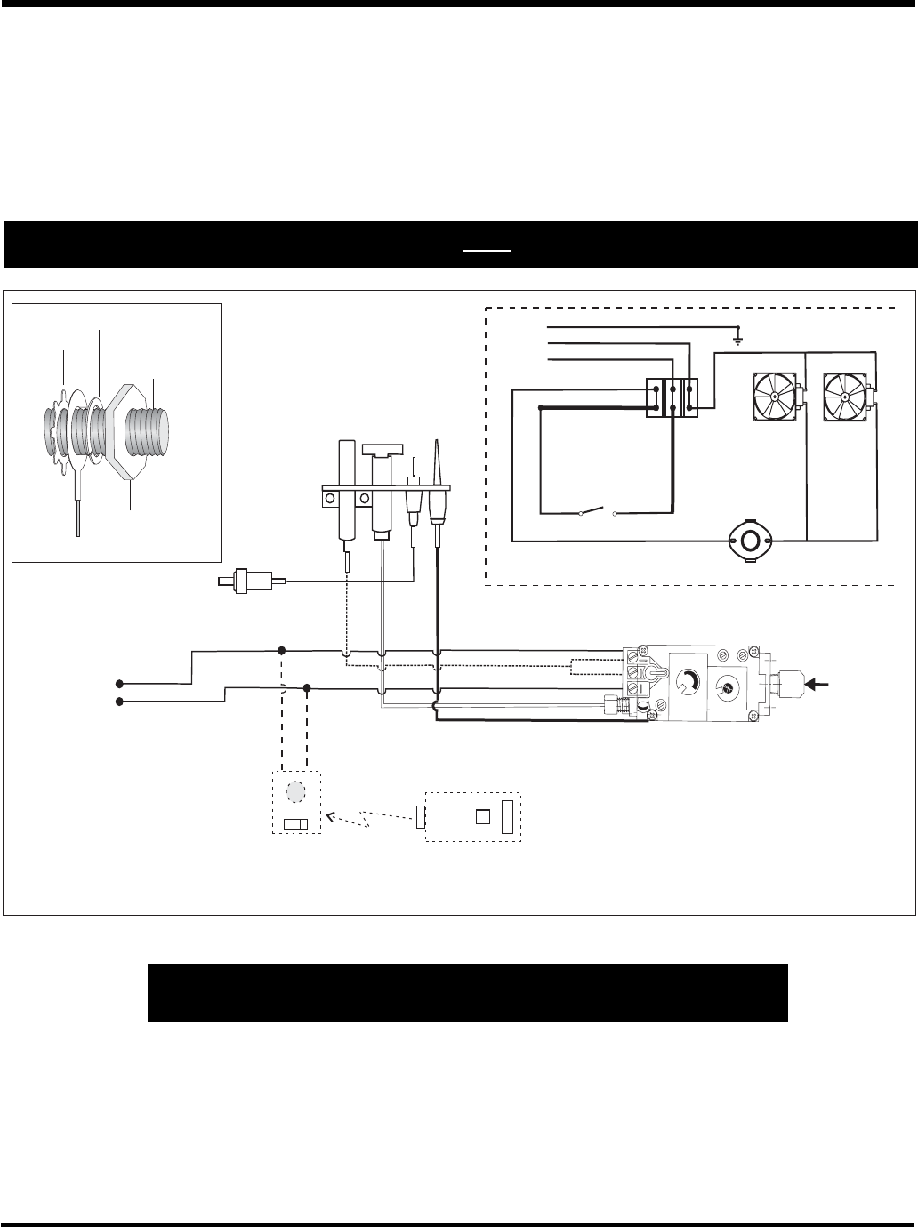
WIRING DIAGRAMS
Caution: Ensure that the wires do
not touch any hot surfaces and are
away from sharp edges.
CAUTION: Label all wires prior to disconnection when servicing controls.
Wiring errors can cause improper and dangerous operation.
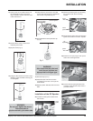
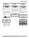
INSTALLATION
No electrical power supply is required for the
gas control to operate. 120 Volt AC power is
needed for the fan switch and blower. The fan
can be hard wired if desired. A terminal block
is provided on the left hand side of the unit.
A three wire power cord can also be used and
plugged into a suitable receptacle.
(Do not cut the ground terminal off under
any circumstances.)
Lockwasher
Ground Wire
Nut
#8 Ground Lug
(for mobile home)
Grounding Lug Detail
Star washer
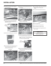
Thermodisc
Green (Ground)
White (Neutral)
Black (Live)
Black
White
Black
White
(*by others)
(*by others)
Black
120 VAC
60HZ
(*by others)
ON
OFF
(*Supplied by others -install
according to local code)
FAN 2
FAN 1
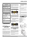
Piezo
Ignitor
To Thermocouple IN
Pilot
Assembly
H
I
L
O
O
F
F
O
N
P
I
L
O
T
Gas Pilot
Thermopile
Thermocouple
Electrode
Remote Transmitter
(Optional)
ON OFF
Regency
Remote Receiver
or Thermostat
(Millivolt) (Optional)
Brown
Red
Black
White
"S.I.T" Valve
To Burner
ON / OFF
Switch
(To THTP)
(To TH)
Gas
In
For NATURAL GAS Units and Units NOT Equipped with DC Spark Boxes