


Regency
®
L676E Direct Vent Gas Fireplace 13
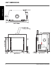
INSTALLATION
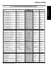
Vent restriction is required for certain venting
installations, see the diagrams in the "Venting
Arrangements" section to determine if they are
required for your installation.
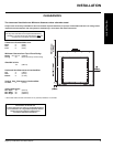
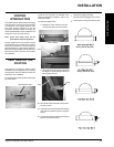
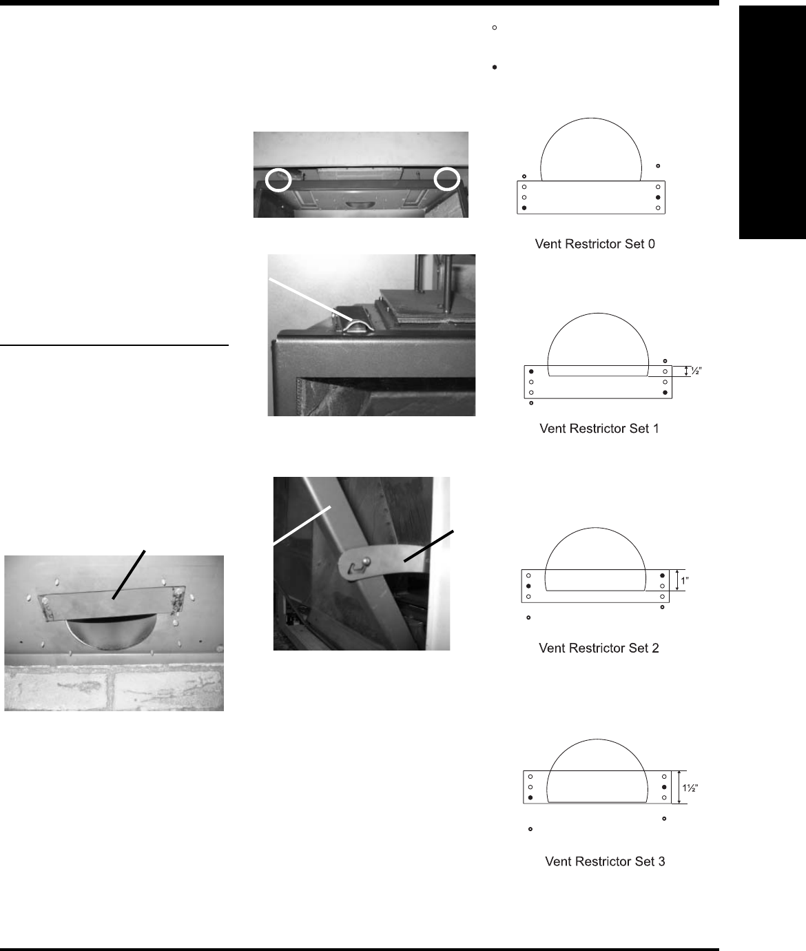
The Vent Restrictor plate is located on the inside
top of the fi rebox.
(factory set for NG units)
INSTALLATION
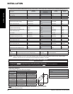
VENT RESTRICTOR
POSITION
Screws for plugging the holes.
(all holes must be plugged with a screw).
Screw holes for fi xing the restrictor plate.
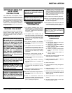
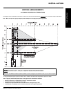
VENTING
INTRODUCTION
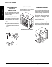
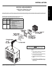
The L676E uses the "balanced fl ue" technology
Co Axial system. The inner liner vents products
of combustion to the outside while the outer
liner draws outside combustion air into the
combustion chamber thereby eliminating the
need to use heated room air for combustion and
losing warm room air up the chimney.
Note: These flue pipes must not be
connected to any other appliance.
The gas appliance and vent system must be
vented directly to the outside of the building,
and never be attached to a chimney serving a
separate solid fuel or gas burning appliance.
Each direct vent gas appliance must use it's own
separate vent system. Common vent systems
are prohibited.
Vent Restrictor Plate
To set the vent restriction as indicated in the
venting arrangements diagrams, refer to the
instructions below;
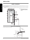
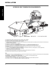
1) Remove the glass door.
a. Release the 2 door latches on the left
and right side at the top of the fi rebox.
b. Swing the door out from the top and release
the hinges on the left and right side of the
door by lifting them up.
Hinge
Door
Latch
Latch Location
2) Remove the screws that hold the vent restric-
tor plate in place.
3) Adjust the vent restrictor plate to the required
vent restrictor position as per the diagrams
shown.
4) Once the vent restrictor plate is in the required
position, secure with screws.
(factory set for LP units)