


20
Regency
®
F39 Room Sealed Freestanding Gas Stove
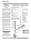
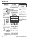
OPTIONAL
WALL THERMOSTAT
A wall thermostat may be installed if desired.
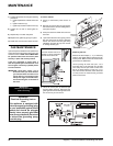
Connect the wires as per the wiring diagrams.
Note that the wires are connected to the "TH"
on the gas valve. Use table below to determine
the maximum wire length:
Note: Preferable if the thermostat is installed
on an interior wall.
Regency
®
offers an optional programmable
thermostat but any 250-750 millivolt rated non-
anticipator type thermostat that is CSA, ULC or
UL approved may be used.
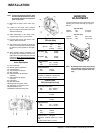
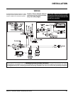
OPTIONAL REMOTE
CONTROL
Use the Regency
®
Remote Control Kit approved
for this unit. Use of other systems may void
your warranty.
The remote control kit comes with a hand held
transmitter, a receiver and a wall mounting
plate.
1) Choose a convenient location on the wall
to install the receiver and the receptacle
box (protection from extreme heat is very
important). Run wires from the fi replace to
that location, use Thermostat Wire Table.
2) Connect the wires as per the wiring diagram
above.
CAUTION
Do not connect the millivolt
wall thermostat wires
to the 240V wires.
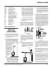
14 GA.
16 GA.
18 GA.
20 GA.
22 GA.
15.24 m
9.75 m
6.10 m
3.66 m
2.71 m
Recommended Maximum Lead Length
(Two-Wire) When Using Wall
Thermostat (CP-2 System)
Wire Size Max. Length
Thermostat Wire Table
INSTALLATION
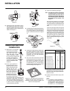
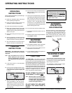
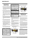
Diagram 1
FRONT DOOR
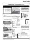
INSTALLATION
(packaged separately)
1) Open the two side panels.
2) Slide the door
onto the two hinge
pins making sure
the two pieces
are fl ush togeth- er.
See diagram 1.
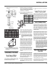
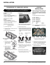
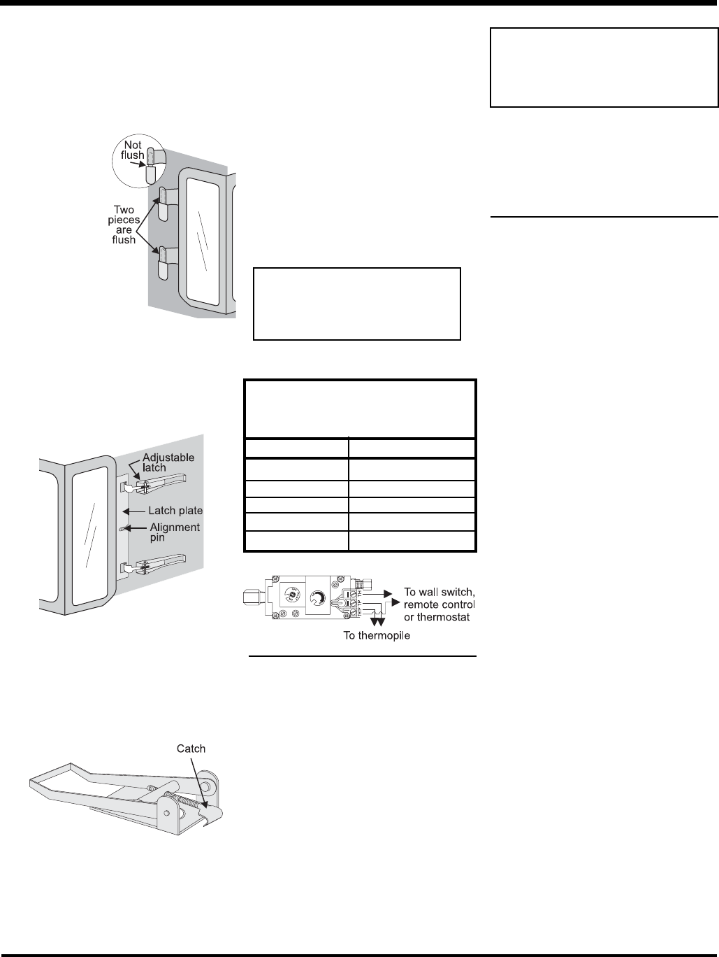
4) The latches should already be at the proper
setting. If they are too hard or too easy
to close, you may want to adjust them by
loosening the latch catch. See diagram 3.
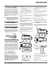
Diagram 2
Diagram 3
5) Remove the blue plastic protective coating
from the glass.
6) Test the seal around the door by placing
a piece of paper between the unit and the
door, close the door and try to pull the paper
out. If it slips out easily, then the door is not
properly sealed. Tighten or loosen the latch.
See diagram 3.
3) Close the door.
The latch plate
must be cen-
tered around the align-
ment pin. See diagram
2. If the latch plate
interferes with the cor-
ner of the stove you
may want to angle the
plate slightly so the door
closes easier.
Note: The door latch may require adjust-
ment as the door gasket material
compresses after a few fi res and
after glass replacement. Turn the
latch catch inward or outward to
loosen or tighten.
CAUTION
Do not connect the millivolt re-
mote control wires to
the 240V wires.
3) Install 3 AAA alkaline batteries in transmitter
and 4 AA alkaline batteries in the receiver.
Install the receiver and its cover in the wall.
Switch the remote receiver to "remote"
mode. The remote control is now ready for
operation.
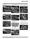
FINAL CHECK
Before leaving this unit with the customer, the
installer must ensure that the appliance is fi ring
correctly. This includes:
1) Clocking the appliance to ensure the cor-
rect fi ring rate (rate noted on label) at 15
minutes.
2) If required, adjusting the primary air to ensure
that the fl ame does not carbon. First allow
the unit to burn for 15 min. to stabilize.
3) Check for proper draft.
CAUTION
Any alteration to the product that causes
sooting or carboning that results in damage
to the exterior facia is not the responsibility
of the manufacturer.