Regency Freestanding Woodstove
8
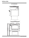
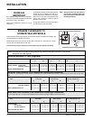
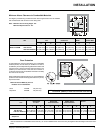
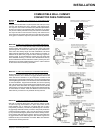
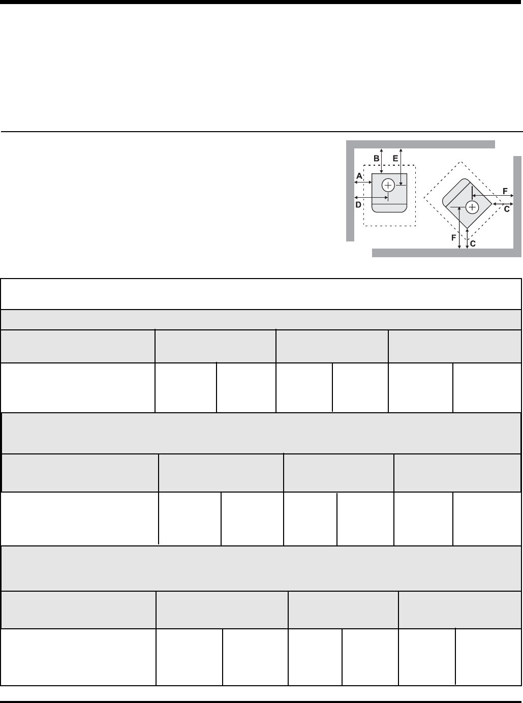
Unit From Unit From Corner From Flue Center-Line
A B C D E F
Medium F2400M with Airmate 15" (381 mm) 5.5" (139 mm) 4" (101 mm) 27" (685 mm) 12" (304 mm) 15.5" (393 mm)
with Rear Defl ector 15" (381 mm) 6.5" (165 mm) 6" (152 mm) 27" (685 mm) 13" (330 mm) 17.5" (444 mm)
Medium S2400M Step Stove 15" (381 mm) 5.5" (139 mm) 4" (101 mm) 27" (685 mm) 12" (304 mm) 15.5" (393 mm)
Residential Installation “C” Vent (Single Wall)
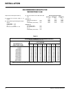
Unit From Unit From Corner From Flue Center-Line
A B C D E F
Medium F2400M with Airmate 16" (406 mm) 11" (279 mm) 6" (152 mm) 28" (710 mm) 17.5" (444 mm) 17.5" (444 mm)
with Rear Defl ector 18" (457 mm) 12" (304 mm) 6.5" (165 mm) 30" (762 mm) 18.5" (469 mm) 19.5" (495 mm)
Medium S2400M Step Stove 16" (406 mm) 11" (279 mm) 6" (152 mm) 28" (710 mm) 17.5" (444 mm) 17.5" (444 mm)
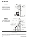
Residential Close Clearance (To be installed with required pipe components)
When the stove is installed as a close clearance residential unit, a listed double wall connector is required from the stove collar to the ceiling
level.
INSTALLATION
Mobile Home Close Clearance (To be installed with required pipe components)
"C" Vent single wall pipe is not approved for Mobile Home installations. (Refer to Mobile Home Instructions.)
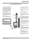
Unit From Unit From Corner From Flue Center-Line
A B C D E F
Medium F2400M
with Airmate 15" (381 mm) 5.5" (139 mm) 4" (101 mm) 27" (685 mm) 12" (304 mm) 15.5" (393 mm)
with Rear Defl ector 15" (381 mm) 6.5" (165 mm) 6" (152 mm) 27" (685 mm) 13" (330 mm) 17.5" (444 mm)
Medium S2400M Step Stove 15" (381 mm) 5.5" (139 mm) 4" (101 mm) 27" (685 mm) 12" (304 mm) 15.5" (393 mm)
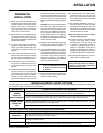
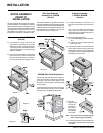
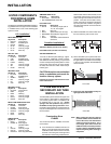
ROOM AIR
IMPORTANT
For installation using room air for combustion,
remove knockout from the pedestal, and/or from
the bottom if using a heat shield.
Mobile home installations require the use of
outside air.
MINIMUM CLEARANCE TO
COMBUSTIBLE MATERIALS
Please read the section below carefully as clearances depend on whether the airmate or the
rear heat defl ector is installed on the stove.
Measurements "From Unit" are from the top plate of the stove to a side wall or to a corner,
and from the rear heat shield to a back wall.
Clearances may only be reduced by means approved by the regulatory authority.
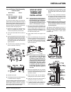
On pedestal units there are two locations where
outside air may be adapted to the unit. If us-
ing the bottom of the pedestal, do not remove
knockout from the rear of the pedestal. Only
remove rear knockout if outside air will be
brought in from the rear.
On leg units outside air can only be brought in
from the bottom of the heat shield.
Note: Once the knockout is removed there
are two tabs remaining. Bend both
tabs out for ease of installation when
attaching outside air.
NOTE: Be aware that local Codes and Regulations may override some clearances listed in this manual.
Check with your local inspector.


