


17Regency
®
E21-2 Gas Fireplace Insert
Conversion Kit# 534-969 from NG to LP
THIS CONVERSION MUST BE DONE BY A QUALIFIED GAS FITTER
IF IN DOUBT DO NOT DO THIS CONVERSION !!
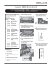
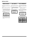
Each Kit contains one LPG
Conversion Kit and one DC
Sparker Kit.
LPG Conversion Kit Contains:
Qty. Part # Description
1 904-163 Burner Orifi ce #54
1 904-529 5/32" Allen Key
1 918-590 Label "Converted to
LPG"
1 908-528 Red "LPG" label
1 910-037 LP Injector (Pilot Orifi ce)
1 910-233 Thermodisc Switch
1 918-482 Instruction Sheet
DC Sparker Kit Contains:
Qty. Part # Description
1 820-475 Bracket DC Sparker
1 820-476 Bracket DC Sparker
1 904-153 Washer #8 External Star
1 904-330 Nut 8-32 Hex
1 904-438 Plug Nylon 0.750 Hole,
Black
1 904-531 Bushing Split Plastic
0.500 in.
1 904-543 Screw 8-32 x 3/4 Pan
Head
2 904-553 Screw #8 x 1/2 Type "B",
Black Oxide
1 910-073 Spark Generator Battery
Holder
1 910-074 Spark Generator Switch
C/W Wire
1 910-078 Battery Size AA
Energizer En91
1 910-199 Clip Wire Holder
1 910-903 Wire Fan To Power Cord
Ground 30 in.
904-781 Velcro Hook, Black
904-782 Velcro Hook, Black
Installation of LPG
Conversion Kit:
1) Turn the unit off and allow it to cool to
room temperature.
2) Shut off gas supply.
3) Unplug or disconnect power source to
stove.
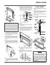
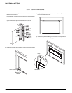
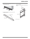
4) Remove glass front (see Door Glass
Replacement section in the manual).
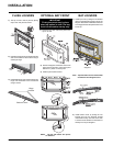
5) Remove logs and brick panels (if
installed).
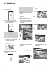
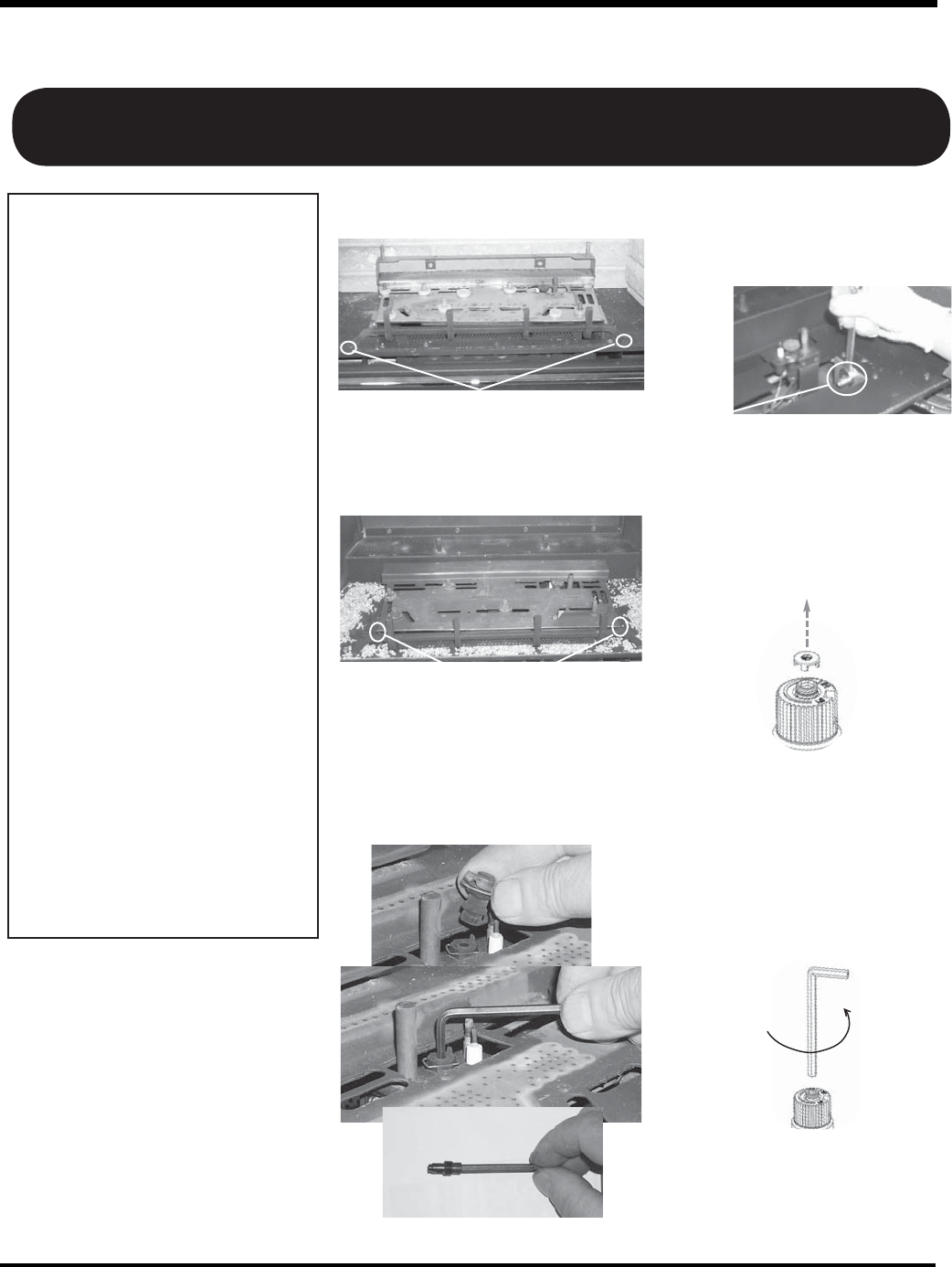
6) Remove the Grate by removing the
screws on each side of the grate.
7) Remove the Burner Tray by removing 1
screw on each side of the tray, then slide
the tray to the left and lift out.
8) Pull off the pilot cap to expose the pilot
orifi ce.
9) Unscrew the pilot orifi ce with the allen
key (provided) and replace with the LP
pilot orifi ce in the kit.
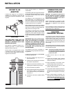
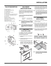
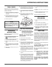
Burner
Orifi ce
Remove the 2 screws holding
the grate in position.
Remove the 2 screws,
push Burner Tray to the left, and lift off.
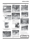
10) Remove burner orifi ce with 1/2"
wrench. Use another wrench to hold
onto the elbow behind the offi ce
Replace with the #54 orifi ce in the Kit.
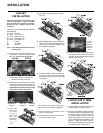
11) Turn control knob to the “OFF”
position.
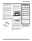
12) Remove the black protection cap by
hand from the high-low knob (Fig.1).
Fig.1
13) Insert a 5/32” or 4mm Allen wrench into
the hexagonal key-way of the screw
(Fig. 2), rotate it counter-clockwise
until it is free and extract it.
Fig.2
INSTALLATION