


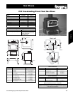
C34 Gas Stove
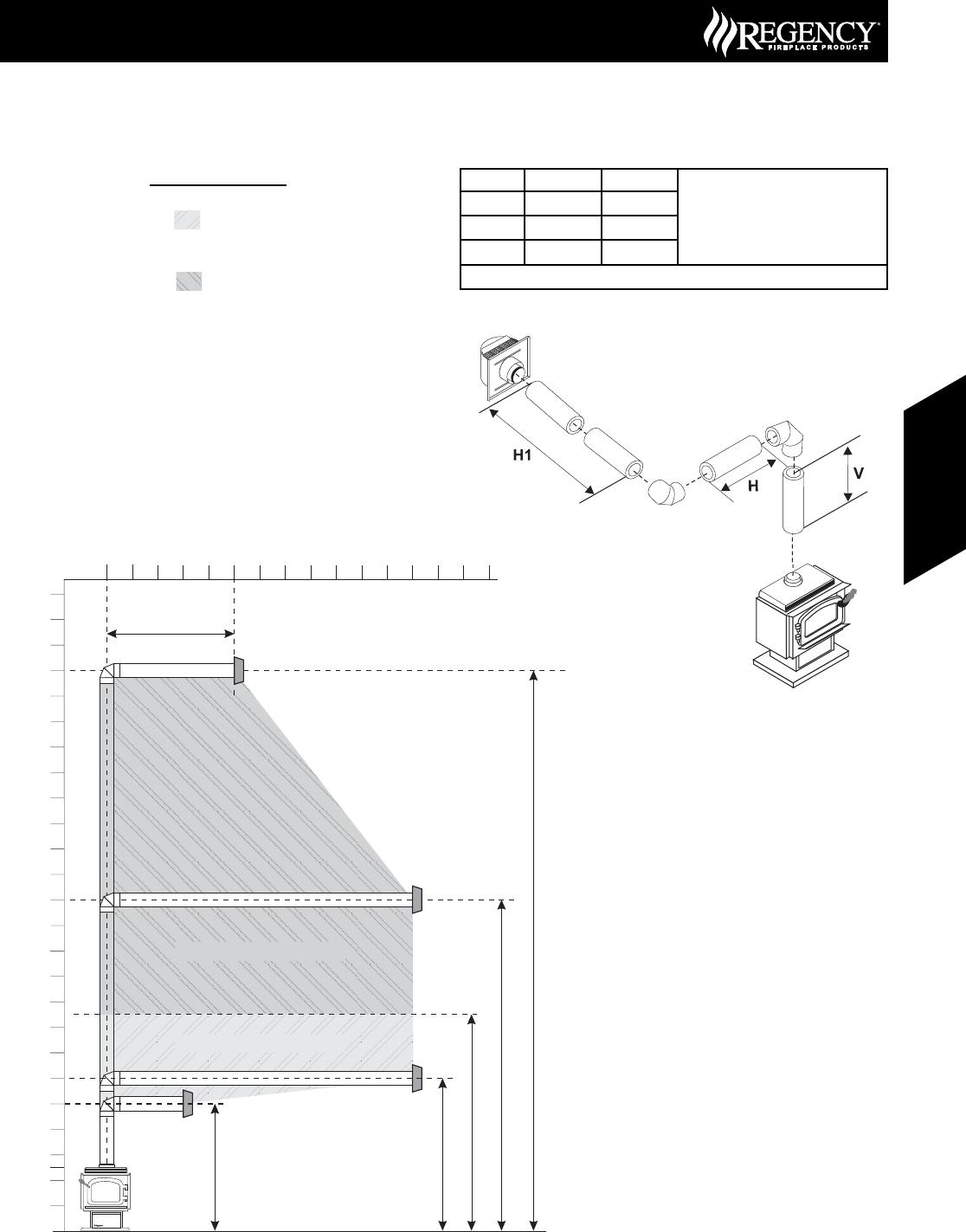
Venting Arrangements - Horizontal
Terminations
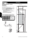
This diagram shows all allowable combinations of vertical runs with
horizontal terminations, using one 90° elbow (two 45º
elbows equal
one 90° elbow).
The lightly shaded area,
6
8
2
0
4
10
0
2
4
6
40
8
10
12
14
16
18
20
22
24
26
28
30
32
34
36
38
12
, in the diagram shows allowable
combinations with Vent Restrictor in position “C” (Center), refer to
page 113.
The darker shaded area,
6
8
2
0
4
10
0
2
4
6
40
8
10
12
14
16
18
20
22
24
26
28
30
32
34
36
38
12
, in the diagram shows allowable
combinations with Vent Restrictor in position “L” (Left), refer to page
113.
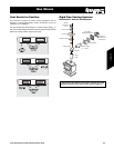
• Maintain clearances to combustibles.
• Horizontal vent must be supported every 3 feet.
• Firestops are required at each floor level and whenever
passing through a wall.
A vent guard may be required as per local codes, refer to page 11 for
“Exterior Vent Termination Locations”.
Note: FPI Direct Vent System (Flex) is only approved for horizontal
terminations.
Maximum: 30 ft. (9.1m)
Minimum 6 ft.(1.8m)
Max. 5 ft. (1.5m)
Maximum: 13 ft. (4m)
0
2
4
6
8
10
12
14
16
18
20
22
24
Vertical Height (Feet)
6
8
Horizontal (Feet)
2
0
4
10
12
14
Minimum 5 ft. (1.5m)
Maximum: 8’ 6” (2.6m)
Vent Restrictor on posittion “C”
Vent Restrictor on posittion “L”
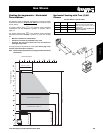
Horizontal Venting with Two (2) 90°
Elbows
Two 45° elbows = One 90° elbow
Option V H + H1 Maximum total pipe length, of all
sections, must not exceed 30 feet.
Total horizontal sections must not
exceed 8 feet.
Minimum of 1 foot between 90°
elbows is required.
A) 4’ Min. 6’ Max.
B) 5’ Min. 7’ Max.
C) 6’ Min. 8’ Max.
Vent Restrictor in position “C” (Center), refer to page 113.
149June 2007 Regency Product Specifi cations Book
Gas Stoves
Gas Stoves