


Page 6 of 13
Location
Before installing the boiler check that the chosen location is suitable, ensuring adequate clearance is
available for both installation and servicing. The appliance must be mounted on a flat vertical wall.
Prepare the Appliance
Remove the front panel by unscrewing the two screws at the bottom of the case. Rotating the case forwards
at the bottom 10 mm and lifting it off in an upward direction.
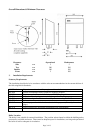
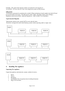
Preparing the Wall
Using the diagrams earlier in these instructions, or the appliance as a template, mark four positions on the
wall were the fixing screws will fit. Ensure the appropriate clearances for the boiler have been established.
The wall should be drilled with a 4 mm masonry drill after ensuring there are no electric cables within the
hidden fabric of the building.
Insert the rawl plugs followed by the two upper screws. These should be inserted to within 2 mm of the wall.
Mark a suitable position for the pressure relief discharge pipe ensuring a suitable position outside. Drill
through the wall with a 16 mm minimum diameter masonry drill to accept a 15 mm copper pipe. This is for
the pressure relief discharge.
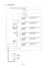
Mounting the Boiler
Locate the boiler onto the two screws. Fit the two lower screws and tighten all 4 screws to secure the
appliance in position.
Water Connections
Refer to Section 3 for detailed information.
The boiler flow and return service valves should be connected directly to the heating system. The flow is on
the right hand side, the return being on the left hand side. Each is marked accordingly.
A suitable method of filling the system should be fitted to the system. The method used for filling the system
must comply with the local Water Authority Regulations. A drain cock should be fitted to the lowest point of
the system. The pressure relief outlet should be connected to a suitable outside position.
Electrical Connections
The appliance is supplied with a 2 m length of 3-cone cable with a normal plug pre-wired. This can be
plugged directly into a suitable 220 - 240V ~ 50 Hz, ring main 13 A wall socket.
If required, the plug in timer supplied can be added to control the appliance on / off periods.
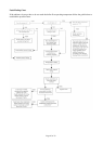
5. Commissioning & Testing
The front cover to the boiler should now be replaced.
Fill and flush the system with all the valves open. Refill the system and check for soundness. Vent the
system, including each radiator and the boiler. At this point the heating system should have been thoroughly
flushed with cold water, filled and vented to a pressure of 0.5 bar cold and be free from leaks.
Note: With the appliance switched on and the thermostat set at the lowest (off) position the pump will
circulate water around the system but the halogen bulbs are prevented from operating.
Plug in the boiler and switch on the electrical supply. Switch the appliance switch on and turn the control
knob to high. The pump should start to circulate water around the system and the Halogen bulbs will start to
heat the water. A thermostat within the boiler will control the temperature of the water as set on the control
knob.