Please also take into account any fitting that could restrict flow such as water meters, softeners etc.
Connection to the unit – Use 22mm compression for all connections. Use gunmetal, DZR or brass fittings,
noting local water conditions.
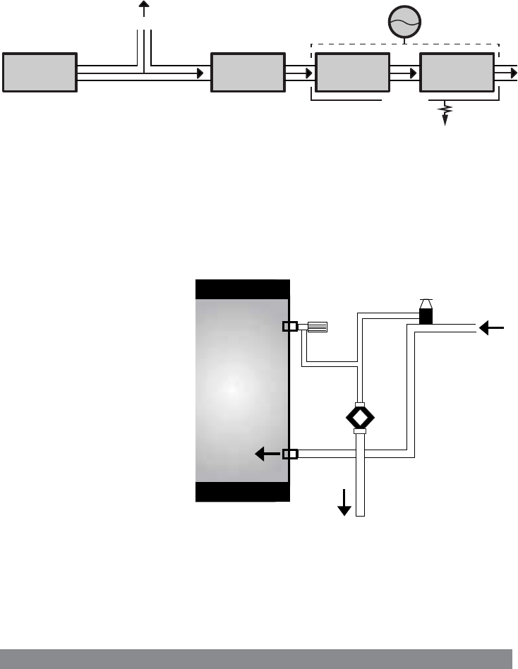
COLD MAINS COMPONENT LAYOUT
No valve is to be fitted between the expansion valve and the cylinder, except a drain point.
It is recommended that a stop cock is fitted to the above to facilitate servicing. Install before the
pressure reducing valve. Always fit a drain tap in an appropriate position for drain down as low as
possible.
DON’T USE MONOBLOC MIXERS IF THE COLD SERVICE IS UNEQUALISED AS IT WILL BACK – PRESSURISE
THE UNIT AND RESULT IN DISCHARGE.
PRESSURE REDUCING
VALVE/FILTER
NON RETURN VALVE PRESSURE GAUGE
EXPANSION VESSEL
(OPTIONAL)
DRAIN POINT
EXPANSION VALVE
COLD TAPS
COLD FEED
22mm
EXPANSION
VALVE
22mm
TUNDISH
15mm
15mm
PRESSURE AND
TEMPERATURE
RELIEF VALVE
2
DISCHARGE
Both the pressure and temperature
relief valve fitted to the unit and
the expansion valve supplied loose
must be arranged to comply with
G3 regulations and each discharge
into an open (visible) tundish.
A 300mm vertical drop of 22mm
diameter pipe must be fitted to the
tundish.
NB: THE TUNDISH AND DRAIN
MUST BE POSITIONED AWAY FROM
ELECTRICAL DEVICES.
ALWAYS CONSULT THE REGULATIONS!
IMPORTANT: Discharge arrangements are the responsibility of the installer and reference to current
building regulations should always be made. Applied Energy Products Ltd. offers the foregoing as
guidelines only.
The main purpose of discharge pipework is to allow full flow from relief valves to be accumulated and
safely routed to a point outside the building at low level.
New Stainless imp_alt 2/15/05 12:15 PM Page 3


