


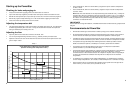

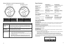
Montaje del Powerstar
ADVERTENCIA:
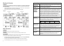
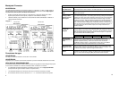
La unidad sólo debe instalarse en la orientación indicada en el Diagrama 1, es decir, se debe montar en
posición vertical con las conexiones de agua situadas en la parte inferior de la unidad. Bajo ninguna
circunstancia se debe instalar la unidad de forma diferente.
• Suelte los tornillos de fijación situados en la tapa delantera y extraiga la cubierta de la unidad.
Sujete la placa posterior contra la pared y marque los cuatro orificios de montaje.
• Taladre los orificios y fije la unidad con los cuatro tornillos de madera suministrados o mediante un
método alternativo adecuado.
Diagram 1
AE115 Unit AE125 Unit
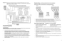
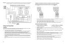
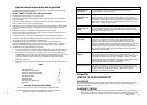
Conexiones de agua
ADVERTENCIA:
No instale una válvula de retención a menos de 3 m de la entrada.
ADVERTENCIA:
No aplique calor ni suelde en las conexiones o tuberías si ya están conectadas directamente a la unidad.
DESCARGO DE RESPONSABILIDAD:
En el Estado de Massachusetts, se debe instalar una válvula de seguridad en el lado del agua fría por parte
de un fontanero autorizado con número de autorización MGL 142 Sección 19. P1-09-25
• La unidad debe conectarse directamente al suministro de agua fría y no al de agua precalentada.
(la temperatura del agua de entrada no debe ser superior a 30ºC).
• La unidad debe instalarse con válvulas de cierre en las conexiones de entrada y de salida.
• Se recomienda utilizar conexiones de cobre de ¾" o ½" conexiones flexibles de alta presión.
4
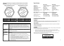
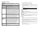
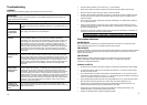
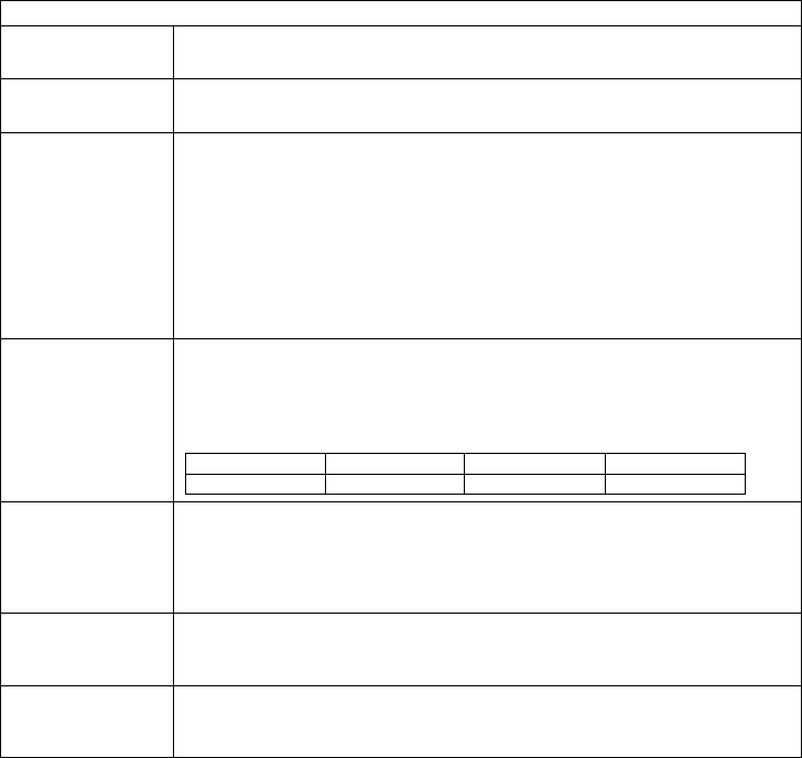
Water too cold – Neon light on
Temperature dial
is turned too low
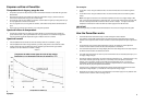
Turn the temperature dial located on the bottom of the water heater clockwise for
hotter temperatures. Refer to Graph 1 for outlet temperature vs. flow rate variance.
Water flow is too
high
Adjust water flow to stay within the water heater’s specifications. See Graph 1 on
Page 8 of this manual.
One or more of the
heating module
thermal cut-outs
has tripped
Shut off the power to the unit, remove the cover and locate therm al cutouts on the
top of each heating module. Try resetting each cutout by pushing the reset button
located in the center of the cutout. Determine and fix the cause of the overheating.
Obstructions in the water path can restrict the flow of water through the heater
causing it to overheat. Verify the heater’s inlet filter screen and all outlets served
by the heater are clear of debris. Ensure the heater is not being fed preheated
water. This water heater is designed for a cold water feed only. If thermal cut out
does not reset, check for continuity through each cutout (Less than 0.5 Ohms). If
any cutout reads more than 0.5 Ohms or open, then it may be defective and
should be replaced.
The power supply
voltage has
dropped
This is likely an issue with the incoming power supply. Have a qualified electrician
measure voltage on the water heater’s terminal block while operating at maximum
flow and maximum temperature setting. The AE115 / AE125 models are rated for
240V and will also operate at 220V or 208V with reduced output. The output will
vary in accordance with the following ratios:
Volts
208 220 240
Output Ratio
0.75 0.84 1.0
The inlet water
temperature is too
cold
Verify the heater is sized appropriately for it’s geographic location. Turn
temperature knob located on the bottom of the water all the way clockwise for
maximum temperature setting. Ensure flow rates are within the heater’s
specifications. Refer to Graph 1 on Page 8 of the manual. Use of an isolation
valve on the hot water outlet to control flow rate is recommended.
One of the power
supplies is not on
Have a licensed electrician verify adequate voltage on the terminal block inside
the water heater. Verify circuit breakers serving the heater are not tripped. See
the “Electrical connections” section on Page 5 of this manual.
Premature element
failure
Shut off power to the unit and remove cover. Use an ohmmeter to verify correct
resistance on each element. If readings are different than listed specifications on
Page 14, contact Technical Support (866) 330-2729 for further instruction.
13