18
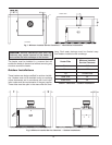
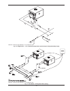
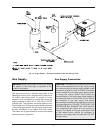
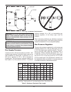
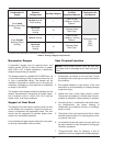
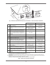
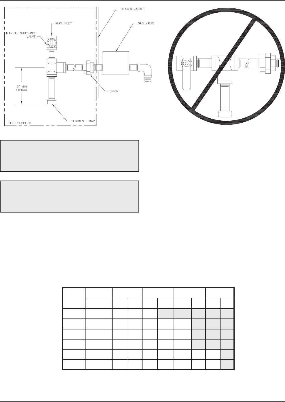
Fig. 13: Sediment Trap Orientation
Gas Supply Pressure
A minimum of 4 in. WC and a maximum of 10.5 in. WC
upstream gas pressure is required under load and no
load conditions for natural gas. A minimum of 11 in.
WC and a maximum of 13 in. WC is required for
propane gas. The gas pressure regulator supplied on
the heater is for low pressure service. If upstream
CAUTION: Do not use Teflon tape on gas line pipe
thread. A pipe compound rated for use with gas
systems is recommended. Apply sparingly only on
male pipe ends.
CAUTION: Support gas supply piping with
hangers, not by the heater or its accessories. Ensure
the gas piping is protected from physical damage
and freezing where required.
pressure exceeds 14 in. WC, an intermediate gas
pressure regulator, of the lockup type, must be
installed.
When connecting additional gas utilization equipment
to the gas piping system, the existing piping must be
checked to determine if it has adequate capacity.
Gas Pressure Regulator
The gas valve pressure regulator(s) on the heater are
nominally preset at 3 in. WC for natural gas, and 10.0
in. WC for propane gas manifold pressure. The pres-
sure at the gas valve outlet tap, measured with a
manometer, while in operation should be 3.0 in. ± 0.3
in. WC (HI), and 1.0 in. ± 0.1 WC (LO) for natural gas
and 10.0 in. ± 0.1 in. WC (HI), and 3.5 in. ± 0.1 in. WC
(LO) for propane gas. If an adjustment is needed, turn
the adjustment screw clockwise to increase pressure
or counter-clockwise to decrease pressure.
Model
No.
Input 3/4” 1” 1-1/4” 1-1/2”
(KBTUH) N P N P N P N P
HD101 100 105 385 340
HD151 150 50 180 160 530 600
HD201 199 30 95 95 355 360
HD251 250 20 50 60 230 240
HD301 299 15 35 45 170 170 550 360
HD401 399 5 20 25 80 100 365 210
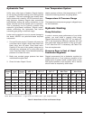
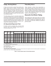
Table G: Maximum Equivalent Pipe Length
Natural gas – 1,000 BTUH per ft
3
, .60 specific gravity at 0.5 in. WC pressure drop
Propane gas – 2,500 BTUH per ft
3
, 1.50 specific gravity at 0.5 in. WC pressure drop


