5
Gas Supply Pressure
A minimum of 5.0 in. WC and a maximum of 10.5 in.
WC upstream gas pressure is required under load and
no-load conditions for natural gas. A minimum of 8.0
in. WC and a maximum of 13.0 in. WC is required for
propane gas. The gas pressure regulator(s) supplied
on the heater is for low-pressure service. If upstream
gas pressures exceed 14.0 in. WC, intermediate gas
pressure regulators, of the lockup type, must be
installed.
When connecting additional gas utilization equipment
to the gas piping system, the existing piping must be
checked to determine if it has adequate capacity for
the combined load.
The gas valve pressure regulator(s) on the Hi Delta
heater are nominally preset at 3.5 in. WC. The pres-
sure regulator on the FlexGas propane system is
nominally set at 2.2 ± 0.1 in. WC. This can be verified
by measuring the propane gas pressure at the upper
manifold pressure tap shown in Fig. 5. The pressure at
the gas valve(s) outlet tap, measured with a manome-
ter, while in operation should be 3.5 ± 0.1 in. WC for
natural gas. A nominal pressure of 1.3 in. WC will be
observed at the individual heater gas valve outlet taps
on propane gas. See Fig. 5 for gas pressure measure-
ment locations.
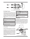
Bleeds/Vents
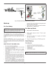
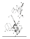
This FlexGas gas train is equipped with an propane
gas regulator and low gas pressure switch (optional on
302BD-902BD) which may need to be vented to the
outdoors as required by state and local codes. If these
components are required to be vented, the cover must
be removed and vent lines installed into the compo-
nents and ran to a suitable location outside the
building in compliance with the NFGC. See Fig.3.
CAUTION: Do not use Teflon tape on gas line pipe
thread. A pipe compound rated for use with natural
and propane gases is recommended. Apply sparing-
ly only on male pipe ends, leaving the two end
threads bare.
CAUTION: Support gas supply piping with hang-
ers, not by the heater or its accessories. Make sure
the gas piping is protected from physical damage
and freezing, where required.
Low Gas Pressure Switch
(Optional on 302BD-902BD)
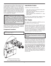
Fig. 2: Gas Supply Connection - Top View
NOTE: DO NOT adjust the FlexGas propane regu-
lator setting without verifying proper operation
including the use of a flue gas analyzer.
Fig. 3: FlexGas Cover Removal & Vent Locations
CAUTION: DO NOT adjust the individual heater
gas valve pressure settings when firing with
propane gas. Propane adjustments (if neces-
sary) should ONLY be made to the FlexGas
propane regulator.


