50
SECTION L CONTROLS
WARNING: Installation, adjustment and service of boiler controls including timing of various operating
functions must be performed by a qualified installer or service agency. Failure to do so may result in
control damage, boiler malfunction, property damage, personal injury, or death.
WARNING: Turn off the power to the boiler before installation, adjustment or service of the Central Point Wiring
board or any boiler controls. Failure to do so may result in board damage, boiler malfunction,
property damage, personal injury, or death.
CAUTION: This appliance has provisions to be connected to more than one (1) supply source. To reduce the risk
of electric shock, disconnect all such connections before servicing.
CAUTION: Risk of electric shock. More than one (1) disconnect switch may be required to de-energize the
equipment before servicing.
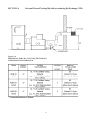
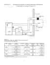
CENTRAL POINT WIRING (CPW)
Central Point Wiring is an advanced control integration technique that provides complete boiler diagnostic capability
and greatly simplifies troubleshooting. At the heart of CPW is the Operations Status Center, which is comprised of two
different circuit boards: the CPW board and one or more U-2 Diagnostic Boards.
THE CPW BOARD
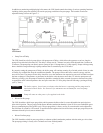
The Central Point Wiring (CPW) board serves as the central tie point for connecting all other control components in the
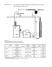
boiler. The CPW board provides boiler operating status and fault indication using eight LEDs which function as described
in Table L-1
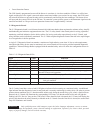
Table L-1 CPW Board LED Indicators
Light Color Indication
Power Green 24 VDC is applied to the system
System Error Red Overload current on the board. Board is disabled.
Pump Green Boiler Pump is energized.
Pilot Yellow Power applied to the Pilot Gas Valve. (PV signal on.)
Main Gas Green Power applied to Main Gas Valve. (MV signal on.)
Call for Heat Green Thermostat is closed. Call for heat present.
Service Red (Flashing) One or more of the safeties are open. Refer to U-2 Board
Blower Green Blower is energized.


