Page 16
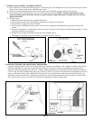
13. BLOWER #1 (SMALL CONVECTION BLOWER)
This blower is located on the right side of the insert. When
the insert is pulled out onto the hearth, the blower is
accessible through a removable access panel. This blower
comes on automatically when snap disc #1 heats up. The
blower’s function is to deliver heat from the insert into the
room.
14. BLOWER #2 (NEGATIVE DRAFT BLOWER)
This blower creates a negative pressure (vacuum) in the
firebox. It extracts all of the exhaust out of the firebox and
sends it into the venting system. The blower is located on the
left side of the insert. When the insert is pulled out onto the
hearth, the blower is accessible through a removable access
panel.
15. BLOWER #3 (LARGE CONVECTION BLOWER)
This blower is located on the left side of the insert, and is
accessible through the left side panel. It is the larger of the
two convection blowers, and pushes air past the cast heat
exchanger and into the room. This blower, along with blower
#1, will come on within 10-15 minutes of ignition.
16. FEED SYSTEM
The feed system pulls pellets up the feed tube from the hopper,
using a hollow auger spring, and drops them down the feed
chute into the firepot. The feed rate is adjustable; for complete
instructions read the fuel feed system in the cleaning and
maintenance section of this manual. NOTE: The feed motor
will not operate when the front door of the insert is open. If
you are having fuel problems, check the following:
A. Check the ramp in the firepot to see that it is free of fuel or
other materials.
B. Check the set screw on the end of the motor shaft to see that
it is tight and not slipping.
C. Check the electrical power to the motor.
D. Check the vacuum switch hose connections.
17. IGNITER
A. The igniter is located in the chamber at the bottom of the
firepot. It is only on during the ignition cycle, and is
usually on for the first two minutes and not more than
four minutes.
NOTE: The element on the igniter is extremely
brittle. Be very careful in handling it.
B. Check the wire leads to the igniter for loose or bad
connections (ceramic wire nuts).
NOTE: Unplug insert before checking wire nuts.
18. FIREPOT
A. Clean the firepot (see section on cleaning and
maintenance on page 13).
B. Make sure the cleanout plate in the bottom of the firepot is
pushed in all the way.
C. Check the gasket between the firepot and the firebox bottom.
A bad seal will affect the ignition time and the flame height.
19. DOOR GASKET
Check the door gasket to see that the door is completely closed
and there are no air leaks. This can be done by closing the door
on a piece of paper and checking that the paper is firmly held in
place. You should have resistance when you try to pull the paper
away.
NOTE: If no resistance is found, the door handle assembly
needs to be adjusted or rope seal needs to be replaced.
20. HEAT EXCHANGER
There is one cast heat exchanger mounted on the right side of
the firebox. Refer to cleaning and maintenance section in this
manual for cleaning instructions (page 13).


