16
PV500-47C 06/12
8 COMBUSTION AND VENTILATION AIR
Provisions for adequate combustion and ventilation air to the mechanical room must be in accordance with Section
5.3 “Air for Combustion and Ventilation” of the latest edition of the National Fuel Gas Code, ANSI Z223.1 and/or
CAN/CSA B149, Installation Codes or applicable provisions of the local building codes.
8.1 Equipment Located In Confined Spaces
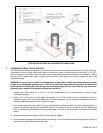
Equipment located in confined spaces requires two openings installed within 12” (30.5 cm) from the top and bottom
of the room to assure adequate combustion air and proper ventilation. The total input of all gas utilization equipment
installed in the room must be used to determine the required minimum air volume needed for combustion,
ventilation and dilution of flue gasses.
All Air From Outdoors:
Each opening requires a minimum free area of 1 square inch
per 4000 Btu/hr input if directly communicating
with the outdoors or communicating to the outdoors through vertical ducts.
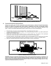
Each opening requires a minimum free area of 1 square inch
per 2000 Btu/hr input if communicating with the
outdoors through horizontal ducts.
All Air From Inside The Building:
Each opening requires a minimum free area of 1 square inch
per 1000 Btu/hr input, but not less than 100
square inches (0.06 m
2)
.
Combination Of Air From The Indoors And From The Outdoors:
Refer to National Fuel Gas Code, ANSI Z223.1 and/or CAN/CSA B149, Installation Codes or applicable
provisions of the local building codes.
NOTE: This unit may be installed with a remote air intake system which uses a make-up air duct to draw
combustion air directly from outdoors.
WARNING: Adequate clean combustion air must be provided to the appliance. Under no circumstances
should the appliance ever be under a negative pressure. Particular care should be taken when exhaust
fans, compressors, air handling units, etc. may rob air from the appliance. The combustion air supply must
be completely free of any chemical or fumes, which may be corrosive to the appliance. Some common
chemical fumes to avoid are fluorocarbons and other halogenated compounds, most commonly present as
refrigerants or solvents, such as Freon, trichloroethylene, perchlorethylene, chlorine, etc. These chemicals,
when in contact with the equipment or when burned, form acids which quickly attack the tubes, flue
collector, stack and other appliance and auxiliary equipment. The result of inadequate clean combustion air
or negative pressure can be premature unwarranted product failure or unsafe operation producing carbon
monoxide that could escape into the building. Exposure to carbon monoxide can lead to injury or death.
8.2 Maximum Allowed Remote Combustion Air Inlet Length (Equivalent Length)
A vertical or horizontal remote air inlet system can be connected to this appliance without modification. The
maximum length of field supplied single wall pipe, such as galvanized ventilation pipe, is shown in the chart below
titled Maximum Air Inlet Duct Equivalent Length. Use metal tape or RTV sealant to seal each pipe joint.
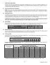
Maximum Air Inlet Duct Equivalent Length
Duct Size 6” Duct 7” Duct 8” Duct 9” Duct
Max Equivalent Length
100 feet 130 feet 250 feet 450 feet
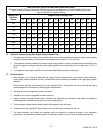
To determine the maximum straight length of duct allowed, use the Duct Fitting Equivalent Length chart below to
find the total equivalent length for all duct fittings in your combustion air system. Then subtract this number of feet
from the total equivalent length allowed in Maximum Air Inlet Duct Equivalent Length chart above. The sum of this
calculation is the maximum length of straight duct allowed. If a longer length is required, repeat the calculation using
a larger duct size. No additional deduction is required for the addition of the duct system terminal.


