22
PV500-44U 06/12
10. A vertical termination less than 10 feet (0.91 m) from a parapet wall must be a minimum of 2 feet (0.61 m)
higher than the parapet wall.
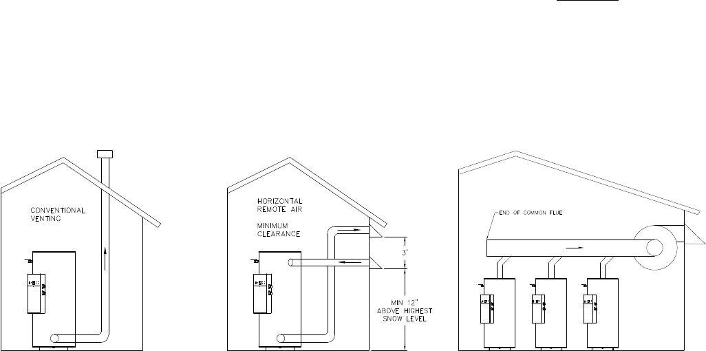
9.6 Combining Category IV Vents
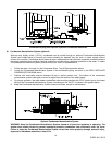
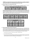
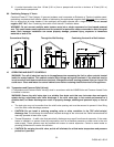
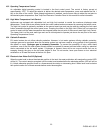
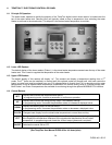
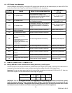
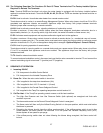
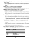
Combined Power VT Plus Category IV gas vent systems must incorporate an Exhausto or Tjernlund variable speed,
modulating, mechanical draft inducer capable of maintaining the appropriate negative draft at the end of the common
flue, to assure that all water heaters in the combined vent system operate with a negative draft. Do not exceed
negative 0.25” W.C. See “Combining Vents with a Draft Inducer” illustration below.
WARNING: Do not connect multiple water heaters vents into a single unpowered or fixed speed powered
vent. This could cause unsafe operation and the potential for poisonous carbon monoxide to enter occupied
areas. Such improper installation can cause property damage, personal injury, exposure to hazardous
materials or loss of life.
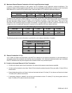
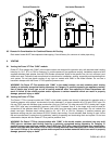
Conventional Venting Through the Wall Venting Combining Vents with a Draft Inducer
10 OPERATING AND SAFETY CONTROLS
WARNING: Turn off all electrical service to the appliance when accessing the limit or other controls located
inside the control cabinet. This cabinet contains High Voltage wiring and terminals. If the electrical service
is not turned off and these terminals are touched, a dangerous shock causing personal injury or loss of life
could occur. Close and fasten the control cabinet cover before restoring electrical service to the appliance.
10.1 Temperature and Pressure Relief Valve(s)
A Temperature and Pressure Relief Valve(s) sized in accordance with the ASME Boiler and Pressure Vessel Code
is installed in the tank.
WARNING: Secure the relief valve pipe to a suitable floor drain such that very hot water does not openly
splash during a significant relief valve discharge. If the relief valve pipe is not routed and secured to a
suitable drain, hot water discharge can result in property damage, scalding and personal injury or loss of
life.
The drain pipe may not be smaller than the relief valve opening and must be secured to prevent it from lifting
out of the drain under discharge pressure.
CAUTION: Do not install a reducing coupling, valve or other restriction in the T&P relief valve(s)
discharge line. The discharge line shall allow complete drainage of the valve and line. Relief valves should be
manually operated at least once a year.
Thermal Expansion - A relief valve that periodically discharges may result from thermal expansion, if the water
heater is installed in a system closed by components, such as a backflow preventer or check valve in the cold
water supply. These systems must be provided with means to control expansion. Contact a water heater or
plumbing professional to resolve this situation.
CAUTION: Do not plug the relief valve, as this will eliminate the critical water temperature and pressure
protection it provides.


