


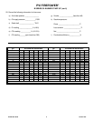

PV500-22A 08-98 6 Section 22A
PVI FIREPOWER
SINGLE STAGE B SERIES OIL BURNER ADJUSTMENTS
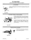
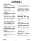
AIR ADJUSTMENT
Loosen the locking screw and move the knob (A) along the scale (B) to the
position wanted and tighten the screw. Check the air adjustment by making a flue
gas analysis.
Figure 22A-2
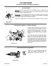
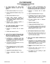
ADJUSTMENT & REMOVAL OF NOZZLE ASSEMBLY
To adjust nozzle assembly (C), loosen screw (D) and move
the nozzle forward or retract by turning the adjustment
screw (E). Line up the pointer on the locating block to the
index position specified in Table 22-2 (pg. 9) for best
results.
To remove the nozzle, remove the burner cover and
disconnect the electrode cables. Separate the nozzle
assembly from the fan housing by loosening the
connecting pipe (F) and extracting the connecting pipe
from the nozzle port.
Figure 22A-3
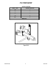
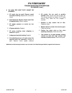
IGNITION ELECTRODE ADJUSTMENT
Check that the measurements between the
nozzle, the ignition electrodes and the pressure
plate correspond to Figure 22-4.
Figure 22A-4