


4
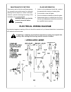
CLEARANCE TO COMBUSTIBLES
ELECTRICAL CONNECTION
A 10 AMP, 220 Volt,50Hz circuit with a properly
grounded outlet is required. Preferably, the stove will
be on a dedicated circuit. Other appliances on the
same circuit may cause the circuit breaker to trip or
the fuse to blow when the heater is on operation.
The unit comes standard with a 6’ (1828mm) long
three wire cord exiting from the rear of the fireplace.
Plan the installation to avoid the use of an extension
cord. If an extention cord must be used, it must be a
minumum 1.0 mm
2
three wire with grounding type
plug connector and rated no less than 1900 Watts.
WARNING: Electrical outlet wiring
must comply with local building
codes and all other applicable
regulations to reduce the risk of
fire, electrical shock and injury.
WARNING: Do not use this
fireplace if any part of
it has been
under water. Immediately call a
qualified service technician to
inspect the fireplace
and replace
any part of the electrical system if
necessary.
ELECTRICAL SPECIFICATIONS
SERVICE INSTRUCTIONS
WARNING: Disconnect power before
attempting any maintenance or cleaning
to reduce the risk of fire, electrical shock
or personal injury
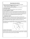
REPLACING LIGHT BULBS
This fireplace uses two clear 220 Volt, 60 Watt, E-14 socket
base light bulbs (small base, chandelier candle type).The
60 Watt bulbs are located under the log set/ember bed. For
convenience, if one of the bulbs burns out, it may be a good
idea to replace both of the light bulbs.
1. Turn off power to the unit by unplugging the power cord.
2. Let fireplace cool if it has been operating.
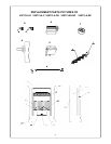
3.Remove the two fixing self-tapping screws on the screen.
Pull the screen upward a little bit, and then out.
4.Remove the two screws that secure the log set in position.
5.Examine the bulbs to determine which bulbs need to be
replaced.
6. While holding the socket, unscrew the defective bulb (s).
7.Install the new light bulb(s) by holding the socket
and screwing them.
8. Reinstall the log set and screen. Follow the above
procedure in reverse order.
9. The diameter of the pilot light bulb is 5mm. If the pilot
light bulb need to be replaced, follow steps 1,2,3,4
above. Then use the pilot light bulb socket w/wiring
assembly replace the primary pilot part, and connect
wires according to primary connection . Then follow
step 8 above.
WARNING: Do not exceed 60
Watts per bulb. Use of higher
rated bulbs may result in a fire
causing property damage and
personal injury.
Back…………………………0mm
Sides……………..…………0mm
Floor……………. .…………0mm
Top………………. .…………610mm
Voltage………………220 VAC/50Hz
Total Amps…………..6.5 Amps
Total Watts…………..1350 Watts
Heater Ratings………1200 Watts