


3.0 Operating the Boiler
8
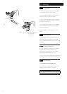
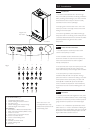
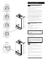
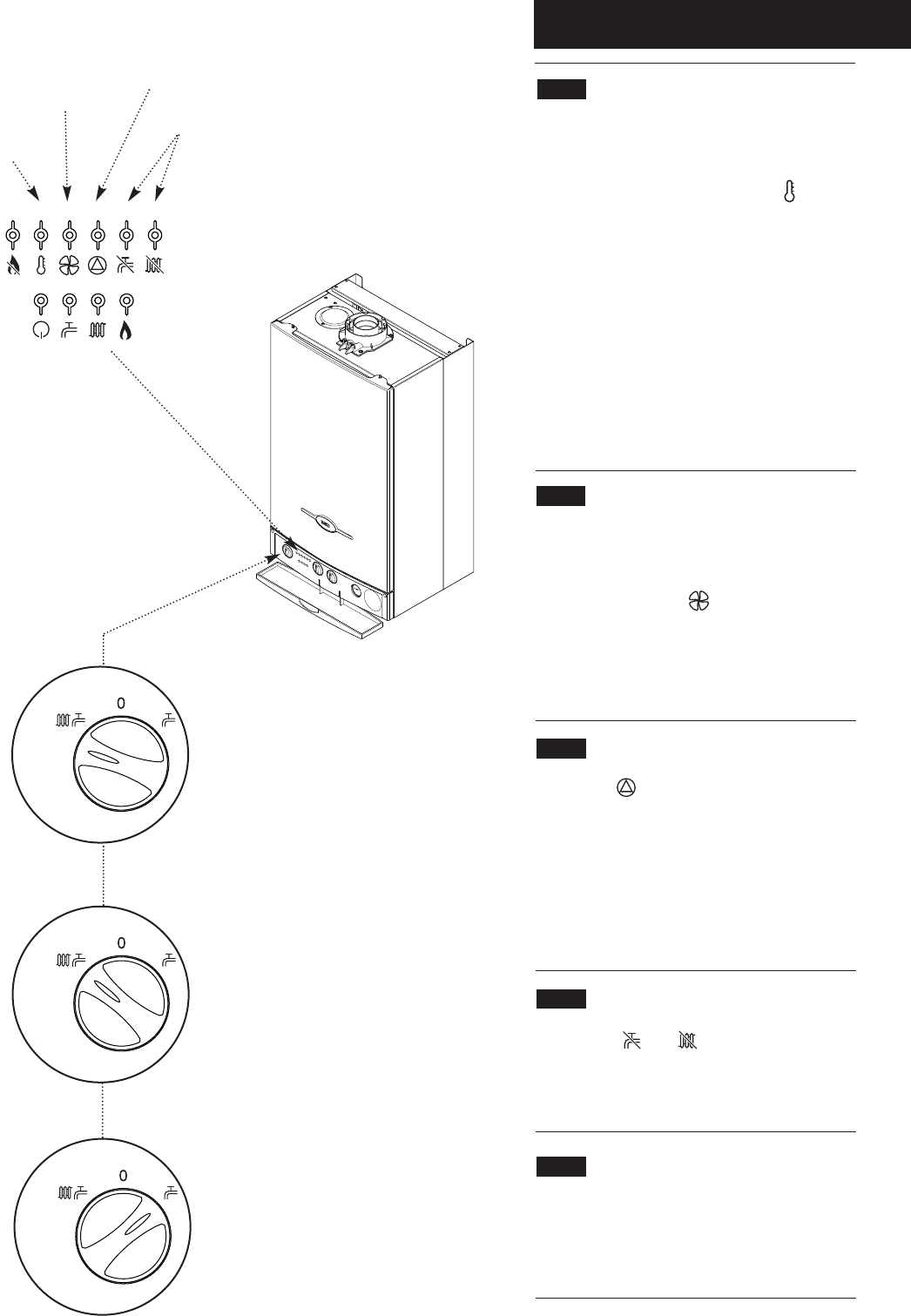
3.4 Safety Thermostats
1. Your Baxi Combi Instant 80 HE or 105 HE is fitted
with additional safety devices, which shut down the
boiler in the event of the system, the boiler or the flue
overheating. The safety thermostat neon ( ) will light
in this instance (Fig. 14).
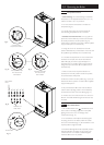
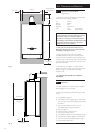
2.
To reset: Turn the selector fully anti-clockwise against
the spring pressure to the ‘Reset’ position for at least
two seconds and release (Fig. 15). Set the selector to the
required position to light the boiler.
3. If after turning the selector to the ‘Reset’ position the
boiler does not relight or the safety thermostat operates
repeatedly, causing boiler shutdown, a fault is indicated.
Your Installer or Service Engineer should be contacted as
soon as possible.
3.5 Air Flow Monitor
1. The boiler is fitted with an air pressure sensing device.
This monitors the flue system.
2. If the neon illuminates ( ) it indicates that the flue
or flue terminal is blocked or obstructed in some way, or
that there is an internal fault. If there is no external
blockage of the flue terminal that can be easily removed
contact your Installer or Service Engineer (Fig. 14).
3.6 Pump Fault or Low Pressure
1. The neon ( ) will illuminate if the circulating pump
is faulty or the system pressure drops below the
minimum requirement (Fig. 14).
2. Check the pressure gauge as described in Section 3.9.
If the pressure is in the normal range, a pump fault is
indicated. Contact your Installer or Service Engineer to
determine the nature of the fault.
3.7 Sensor Fault
1. When the ( ) or ( ) neon is illuminated a fault
on the hot water or central heating temperature sensor
is indicated (Fig. 14). Contact your Installer or Service
Engineer.
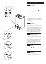
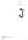
3.8 Pump Protection
1. With the selector switch in either Position (i) or
Position (ii) (Figs. 16 & 17) the pump will automatically
operate for 1 minute in every 24 hours to prevent
sticking.
30
o
40
o
50
o
60
o
70
o
80
o
Air Flow
Monitor Neon
Pump/Low
Pressure Neon
Sensor Fault
Neons
Reset
Reset
Fig. 14
Fig. 16
Fig. 17
Safety
Thermostat
Neon
Reset
Reset Position
Fig. 15