


12
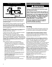
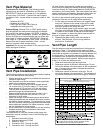
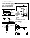
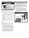
CONCENTRIC VENT TERMINATIONS
For new installations, install 2” or 3” ULC S636 certified PVC or
CPVC concentric vent terminations may be used. See the vent
termination manufacturer’s instructions for complete installation
information or contact customer service at 1-888-479-8324
or techsupport@hotwater.com. For planning purposes, see
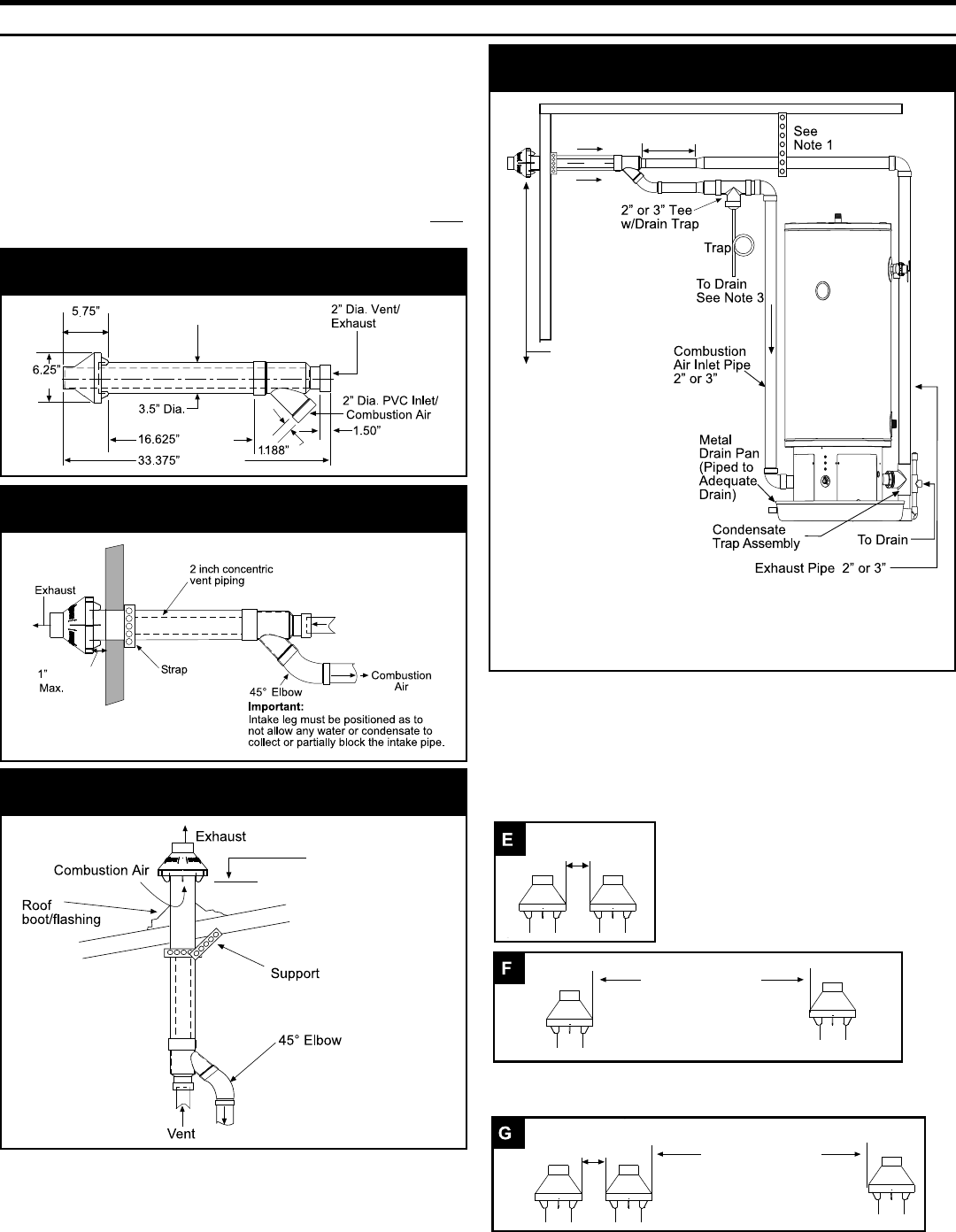
figures 10-13 below for vent terminal specifications.
Note: For replacement installations, previously installed
American Water Heater Company supplied concentric vent kits
are acceptable for use on 100,000-130,000 BTU/Hr models only.
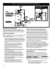
(14.6cm)
(15.7cm)
(8.9cm Dia.)
(42.2cm)
(84.77cm)
(4.8cm)
(3.8cm)
Figure 10: 2 Inch Concentric Vent
(2.54cm)
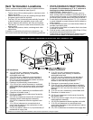
Figure 11: Through the Wall Termination
12” (30.5cm) Minimum
clearance above
anticipated snow level.
24” (61cm) Max.
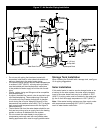
Figure 12: Through the Roof Termination
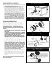
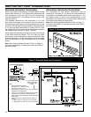
Notes:
1. Support Horizontal Pipe Every
Four Feet (1.2 m). Support
Vertical Pipe Every Six ft. (1.8 m).
2. Increase The 12 Inch (30.5 cm)
Minimum Above Grade To Keep
Inlet Opening Above Anticipated
Snow Levels.
3. Slope All Piping Down Toward
the Water Heater as follows:
´3LSLQJVORSH
´3HU)RRWPPSHUPHWHU
´3LSLQJVORSH
´3HU)RRWPPSHUPHWHU
´FPPD[LPXPZKHQXVLQJ
´SLSH
*
*
*
18”
(45.7cm)
Max.
12” (30.5cm)
Minimum Above
Grade or
Anticipated
Snow Level.
(See Note 2.)
See Note 4
Figure 13: Through the Wall Termination
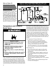
For clarity, T&P discharge line not shown. See the Temperature
and Pressure Relief Valve section for requirements.
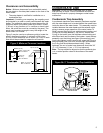
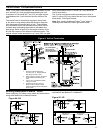
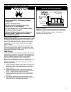
Concentric Venting Multiple Water
Heaters (All Models)
When using two Polaris
®
units, install vent terminations
using either Method E or Method F below:
Note: For installation of more than two Polaris
®
units,
follow the pattern established in Method G.
2” (5.08 cm)
Max.
36” (.9144 m) Min.
2” (5.08 cm)
Max.
36” (.9144 m) Min.
Figure 13E, 13F, 13G