


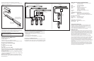

5. Insert the terminator into the last fixture of each light series.
6. Repeat Steps 1 through 5 for each Data Enabler in the installation until
all lights are installed. (See Figure 3.)
Connecting to LSM or VSM (for Ethernet)
For Ethernet control, connect the iColor Accent Powercore fixtures and
the Data Enabler EO to the Light System Manager (LSM) or Video System
Manager (VSM) as described in the LSM or VSM User Guides.
Figure 4 shows the configuration.
Installation Steps for DMX Control
1. Install the Data Enabler EO.
2. Install the fixtures.
3. Address the fixtures using QuickPlay Pro software.
4. Connect to a Philips Color Kinetics or third party DMX512 controller.
Each of these steps are described below.
Installing the Data Enabler EO (for DMX)
See on page 1.
Installing the Fixtures (for DMX)
See on page 1.
Addressing the Fixtures (for DMX)
n o t e : Serial addressing gives you the option of post-installation addressing
multiple fixtures through a single Data Enabler or multiple Data Enablers
using the recorded serial numbers. Refer to the QuickPlay Pro Addressing
and Configuration Guide.
The iColor Accent Powercore fixtures are pre-addressed to light number
1 at the time of manufacture. Address each fixture with a new light number,
as needed, using QuickPlay Pro.
n o t e : During setup of a DMX installation, the QuickPlay Pro software
addresses the fixtures using an Ethernet connection between the PC and
the Data Enabler EO.
Download the QuickPlay Pro Addressing and Configuration Software and
instructions from www.colorkinetics.com/support/addressing.
1. With power disconnected, connect a single iColor Accent Powercore
fixture or a series of fixtures to a Data Enabler EO.
2. Connect the PC running QuickPlay Pro to the Ethernet Port on the
Data Enabler EO.
3. Connect power to the Data Enabler EO.
4. Use QuickPlay Pro to set the light address for each fixture.
Connecting to the DMX512 Controller
For DMX control, connect the iColor Accent Powercore fixtures and the
Data Enabler EO to the Color Kinetics or third party DMX512 controller
as described in the user documentation for the controller. (See Figure 4.)
iColor Accent Powercore Specifications
c ol or ra ng e 16.7 million additive RGB colors; continuously variable
intensity output range
ou tp ut 50-100 lumens (estimated)
s ou rc e Chip-on-board RGB LEDs
vi si bi li ty ra ng e 250º x 180º
h ou si ng Sealed plastic and extruded aluminum
w e i g h t 2-ft (0.61 m) - 4.5 lbs (2.0 kg)
4-ft (1.22 m) - 9.3 lbs (4.2 kg)
8-ft (2.44 m) - 18.0 lbs (8.2 kg)
c on ne cto rs Over-molded, integral male/female connectors
li st in gs UL / cUL, CE
COMMUNICATION SPECIFICATIONS
d ata i n te rfa ce Philips Data Enabler EO (Item#106-000003-06)
c on tr ol Philips full line of controllers, including Video System
Manager, Light System Manager, and other DMX512 sources
ELECTRICAL SPECIFICATIONS
in pu t v o ltag e 100 – 240 VAC 50 – 60 Hz
p o w e r c on su mp ti on 10 W per foot maximum
current .01 A per foot maximum
ENVIRONMENTAL SPECIFICATIONS
temperature r an ge -4ºF to 122ºF ( -20ºC to 50ºC)
protection r a t i n g IP66
Temperature Monitoring
For protection from extreme temperatures, the iColor Accent Powercore has been
designed with a temperature monitoring feature. If operating temperatures rise to
an unsafe level, a compensation circuit is triggered and the iColor Accent Powercore
operation is interrupted causing the lights to turn dull red.
To prevent additional power shut-downs, determine the cause of the overheating and
correct the problem. Power-cycle the system to return to full intensity.
LED Source Life
In traditional lamp sources, lifetime is defined as the point at which 50% of the lamps fail.
This is also termed Mean Time Between Failure (MTBF). LEDs are semiconductor devices
and have a much longer MTBF than conventional sources. However, MTBF is not the only
consideration in determining useful life. Philips Color Kinetics uses the concept of useful
light output for rating source lifetimes. Like traditional sources, LED output degrades over
time (lumen depreciation) and this is the metric for SSL lifetime.
LED lumen depreciation is affected by numerous environmental conditions such as
ambient temperature, humidity, and ventilation. Lumen depreciation is also affected by
means of control, thermal management, current levels, and a host of other electrical design
considerations. Philips Color Kinetics systems are expertly engineered to optimize LED
life when used under normal operating conditions. Lumen depreciation information is
based on LED manufacturers’ source life data as well as other third party testing. Low
temperatures and controlled effects have a beneficial effect on lumen depreciation. Overall
system lifetime could vary substantially based on usage and the environment in which the
system is installed.
Temperature and effects will affect lifetime. Philips Color Kinetics rates product lifetime
using lumen depreciation to 50% of original light output. When the fixture is running at
room temperature using a color wash effect, the lifetime is in the range of 30,000-50,000
hours. This is based on LED manufacturers’ test data. For more detailed information on
source life, please see www.colorkinetics.com/lifetime.
50-foot (15.24 m)
leader cable
to first light in series
Data Enabler EO
Maximum Run length:
The lesser of 15 fixtures
or 100 feet (30.48 m)
Connectors are gender specific.
Ensure that all lights are installed
with connectors facing the same directions
.
Female-to-Male
connection
Terminator
Always terminate last
light in series.
Figure 3
c a u t i o n : Ensure terminator is inserted into last fixture of each series.
Failure to do so may result in minor or moderate injury or property
damage and will void the warranty.
Figure 4
Ethernet
Switch
Ethernet IN
(CA T 5e / RJ45)
Light
System
Engine
PC*
Ethernet IN
(CA T 5e / RJ45)
Ethernet IN
(CA T 5e / RJ45)
ETHERNET DAT A
Data Enabler EO
100 – 240 VA C
Data Enabler EO
100 – 240 VA C
Data Enabler EO
100 – 240 VA C
ETHERNETDMX INDMX OUT
ETHERNETDMX INDMX OUT
ETHERNETDMX INDMX OUT
BLUE
WH/BLUE
ORG
WH/ORG
BLUE
WH/BLUE
ORG
WH/ORG
BLUE
WH/BLUE
ORG
WH/ORG
* PC used for show
authoring and show control.
Maximum run length:
The lesser of 15 fixtures
or 100 feet
Video
System
Engine
- or -
ETHERNETDMX INDMX OUT
100 – 240 V A C
ETHERNETDMX INDMX OUT
BLUE
WH/BLUE
ORG
WH/ORG
DMX OUT
DMX IN
(CA T 5 / RJ45)
DMX IN
Terminator
(CA T 5 / RJ45)
DMX DATA
Data
Enabler
EO
100 – 240 V A C
DMX
Controller
BLUE
WH/BLUE
ORG
WH/ORG
Maximum run length:
The lesser of 15 fixtures
or 100 feet
Data
Enabler
EO