


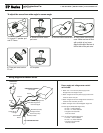

2. Remove motion sensor
pod cover.
3. Remove motion sensor lens. 4. Place narrow lens into pod
cover. Make sure lens is flush
with outside of pod cover.
Align the flat side of the lens w/
the flat side of the pod cover.
5. Place pod cover back on
FP unit.
6. Complete.
Install Instructions For:
To adjust the sensor from wide angle to narrow angle:
Motion Sensor
1.435.647.9555
|
800.647.TUBE
|
www.soundtube.com
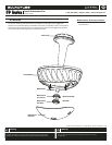
FP Series
FP Series
FP Series
1. Unpack FP speaker pod
and FP Dome.
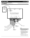
Orange White /
Orange
Blue White (unused)
Green (unused)
Brown White /
Brown
White/Green Signal wire
for 5 Volt ttl signal
Power supply and voltage sensor control
not included.
1. Attach the +12 V from the power supply to the
Orange white and orange wire pair.
2. Attach the ground from the power supply to the brown
white and brown wire pair.
3. Attach the ground from the voltage sensor controller to
the brown and white wire pair also.
4. Attach the signal wire to the white/green single wire.
5 Volt ttl signal (White/Green Signal wire)
• 0 Volts = motion detected
• 5 Volts = no motion detected
• The green and blue/white
wires are unused.
1k to 12 Volt pullup (Blue Signal wire)
• 12 Volts = motion detected
• 0 Volts = no motion detected
• The green and blue/white
wires are unused.
Wiring Diagram for Motion Sensor
Power Source
Cat V Wire From Pod
Voltage Sensor Controller
Blue Signal wire for
1k to 12 Volt pullup
Signal wire
Ground
Ground
Positive
(not included)
(not included)